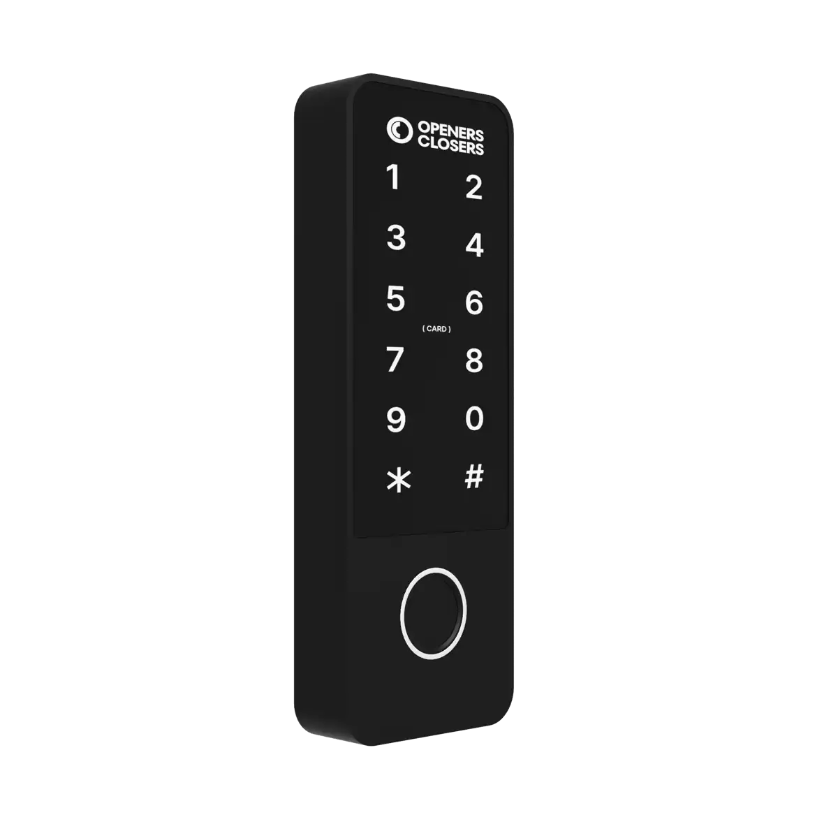
Coded Keypad With Biometrics
AC400 Instruction Manual
Read before installation or use
TopRead Before Installing or Using This Device
This device has been designed for integration into professional access control systems in residential, commercial, or industrial buildings. It must only be installed and handled by qualified technical personnel, in accordance with the manufacturer's specifications. Improper use, unauthorised handling, or incorrect installation may cause serious harm to persons or property, and will void both the warranty and the manufacturer's liability.
Electrical Safety
Before connecting, disconnecting, or intervening with the device, ensure the power supply is completely switched off. Although this product operates at low voltage (e.g. 12–24 VDC), improper handling can cause short circuits, door damage, overheating, or risk of electric shock.
Intended Use and Compatibility
This device is suitable for wooden, metal, or aluminium doors, depending on the model. Certain models are certified for use on fire doors and emergency exits. Always verify the specific certifications and compatibility before installation. Use in environments exposed to water, heavy dust, or aggressive chemical agents is not recommended unless the device is properly certified (e.g. IP65, IP68 etc.).
Maintenance and Use
Do not open, modify, or tamper with the interior of the device. Any unauthorised intervention will automatically void the warranty. Cleaning should be carried out using soft cloths and non-abrasive products. Periodic maintenance by a qualified technician is recommended, particularly in high-usage environments.
Limited Warranty
This product is covered by a commercial warranty against manufacturing defects for the period specified by Openers & Closers. The warranty does not cover normal wear and tear, incorrect installation, tampering, mechanical impacts, or unsuitable environmental conditions. Openers & Closers shall not be held liable for indirect damage, financial loss, or harm resulting from improper or non-compliant use.
Regulations and Compliance
This product complies, where applicable, with relevant regulations in each market (e.g. CE, RoHS, WEEE, UL 294, NFPA-80, EN 14846). Refer to the product labelling and technical documentation to confirm specific certifications.
Disposal and Recycling
This device contains electronic components and must not be disposed of with household waste. It must be taken to an authorised collection point for electrical and electronic equipment (WEEE). The crossed-out wheeled bin symbol indicates this legal requirement. The packaging is recyclable and should be disposed of in accordance with local regulations.
Intellectual Property and Documentation
The content of this manual, as well as the technology integrated into the product, is protected by intellectual and industrial property rights. Its reproduction, distribution, translation, or modification is prohibited without the express authorisation of Openers & Closers.
Dimensions
Top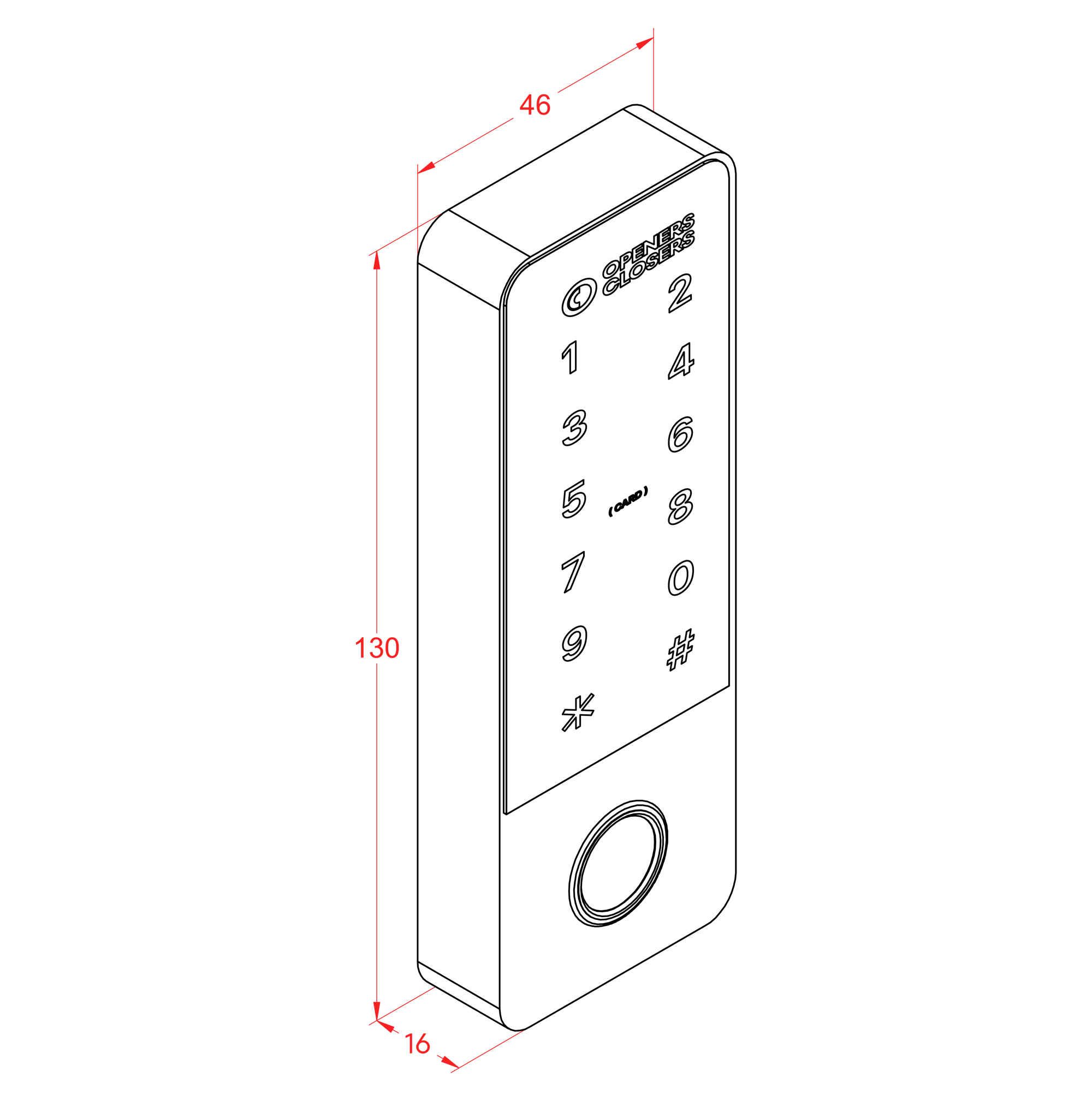
Installation
Top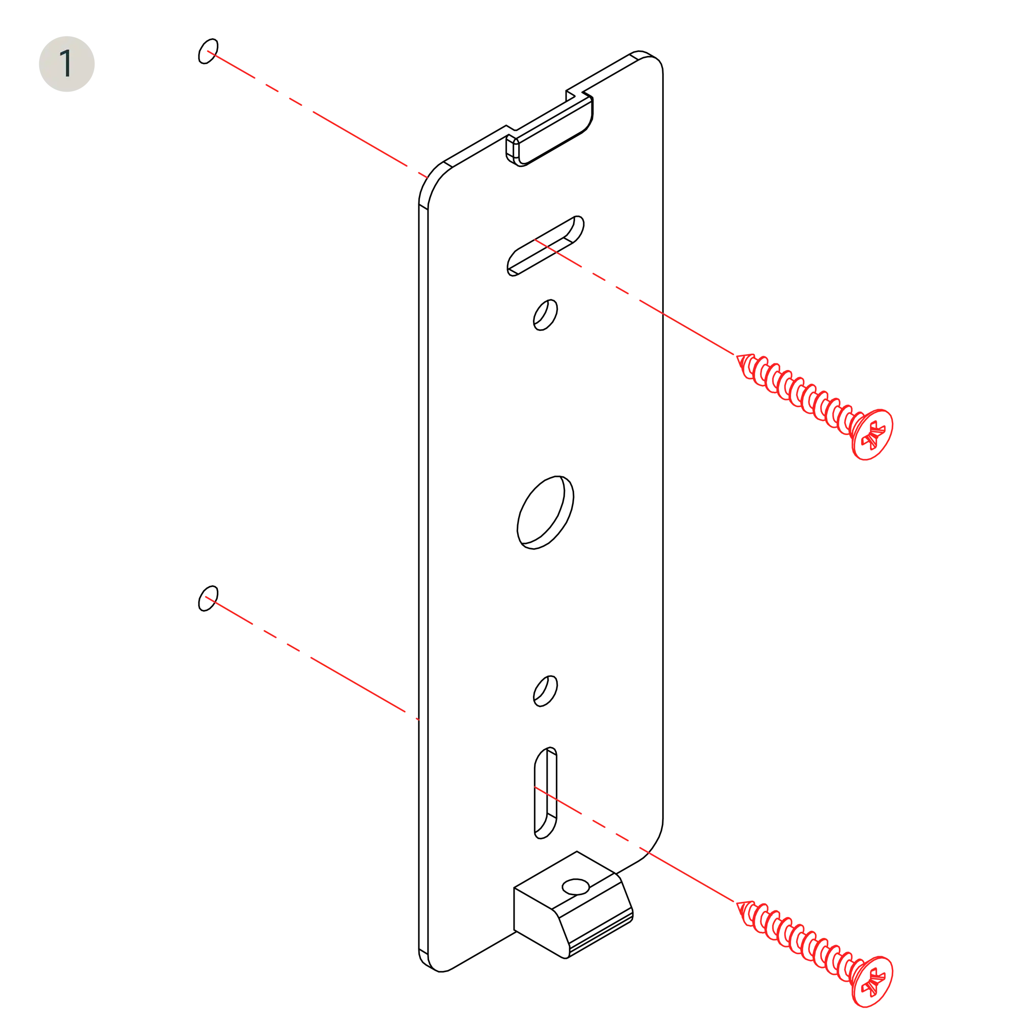

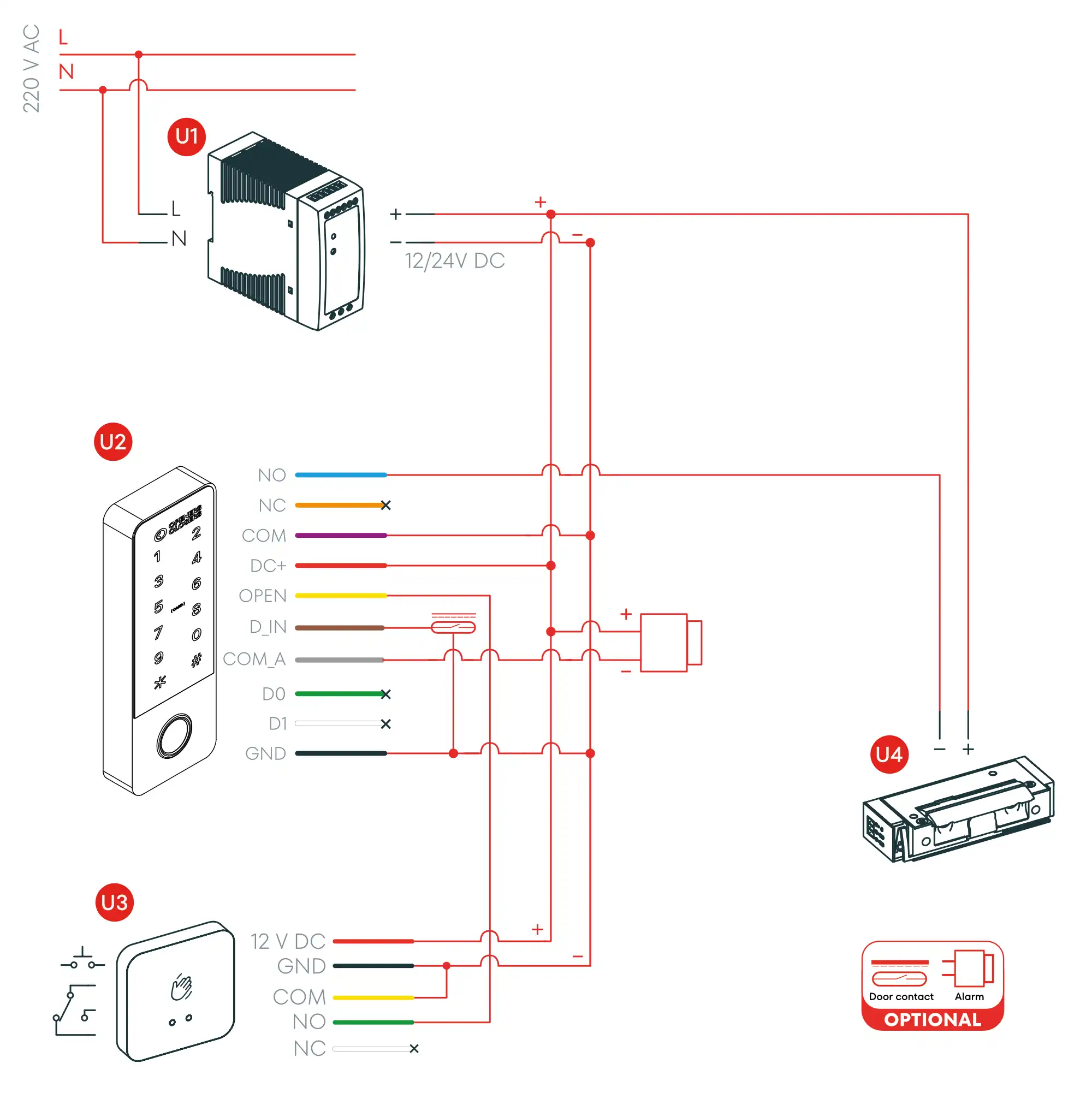
Connection Diagram (Option 1)
Top- U1Power Supply
- U2AC400 Keypad
- U3Push Button (TP Series)
- U4Electric/Electronic Strike Option (Series 1,3,5,8 and 9)
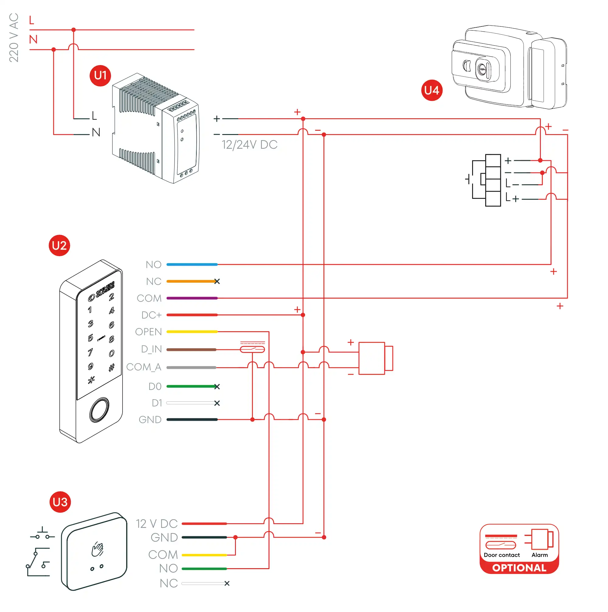
Connection Diagram (Option 2)
Top- U1Power Supply
- U2AC400 Keypad
- U3Push Button (TP Series)
- U4Electromechanical Lock (CE Series)
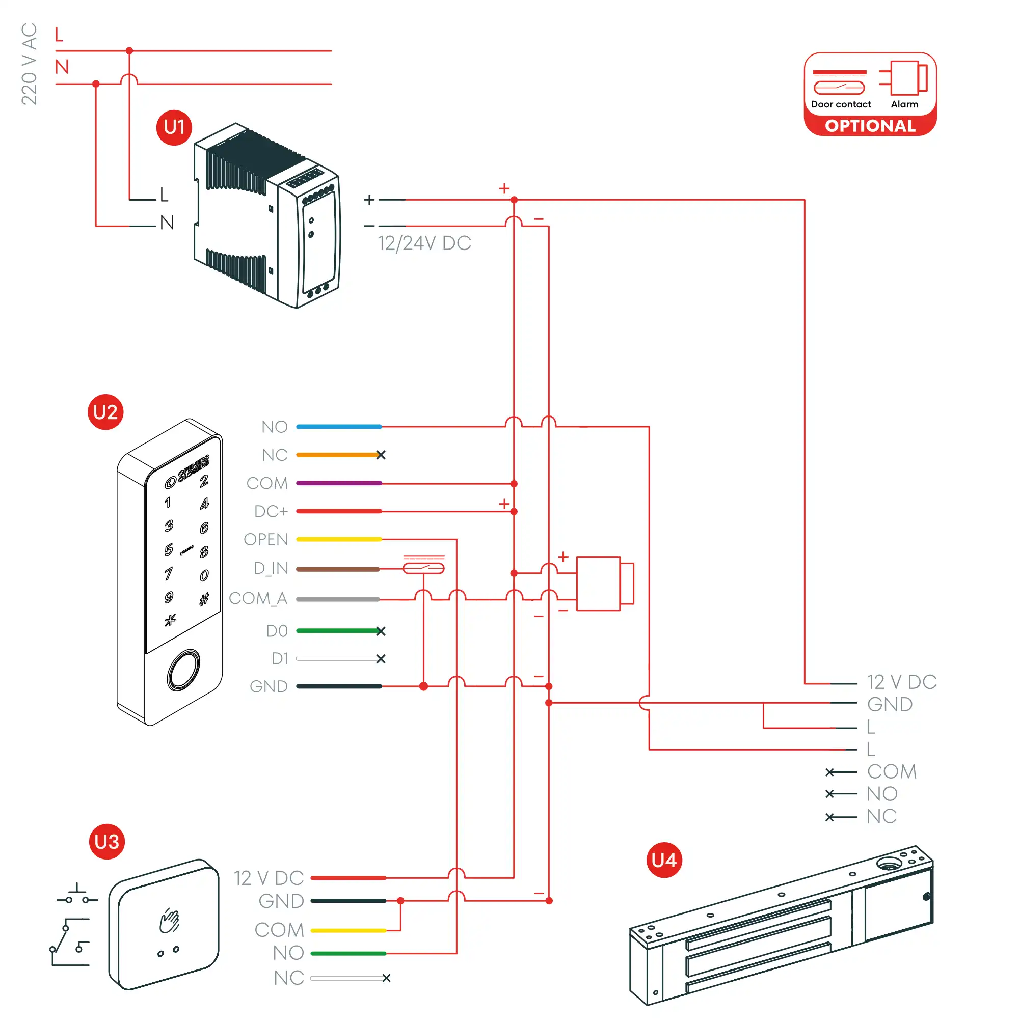
Connection Diagram (Option 3)
Top- U1Power Supply
- U2AC400 Keypad
- U3Push Button (TP Series)
- U4Electromagnetic Strike Option (MEX Series)
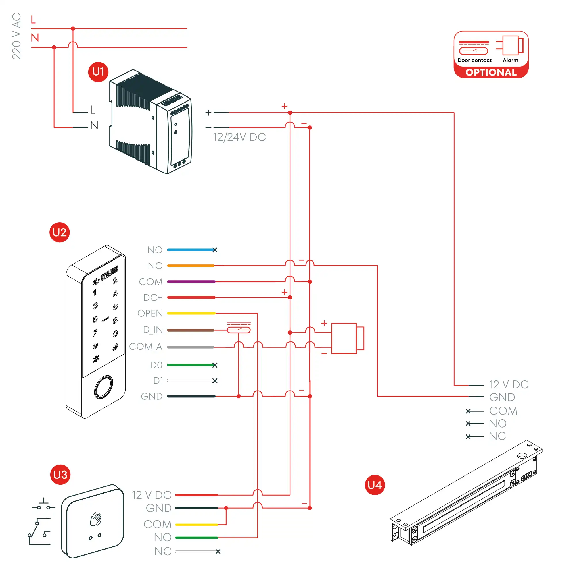
Connection Diagram (Option 4)
Top- U1Power Supply
- U2AC400 Keypad
- U3Push Button (TP Series)
- U4Electromagnetic Strike Option (ME Series)
User Guide
TopLight and Sound Indicators
| State | Red | Green | Orange | Buzzer |
|---|---|---|---|---|
| Standby | ON | - | - | - |
| Enter programming mode | Flash | - | - | - |
| In programming mode | - | Flash | - | - |
| Unlock the door | - | ON | - | 1 beep |
| Wrong operation | Flash | - | - | 3 beeps |
Programming Guide: Programming mode and master code
Top| Action | Command |
|---|---|
| Enter programming mode: | [*] [Master Code] [#] Note: the default master code is 123456 |
| Exit programming mode: | [*] |
Change admin code
| Action | Command |
|---|---|
| Change the master code: | [0#] [New Master Code] [#] [Repeat new Master Code] [#] |
Programming Guide: User Settings
TopAccess mode settings
| Action | Command |
|---|---|
| Unlocking by swiping the card | [4#] [0#] |
| Unlocking by PIN code | [4#] [1#] |
| Unlocking by fingerprint | [4#] [2#] |
| Unlocking by fingerprint-card-PIN code | [4#] [3#] (Factory default) |
| Unlocking by card + PIN code | [4#] [4#] |
| Multi-user unlocking | [4#] [ID numbers#] |
Add Users
| Action | Command |
|---|---|
| Add a card | [1#] Read Card [#] |
| Add a fingerprint | [1#] Press fingerprint (3 times) [#] |
| Add a code | [1#] Enter code [#] |
| Add users in continuous mode | [1#] [Read cards, fingerprints (3 times) or codes consecutively] [#] |
| Add a card for a specific user | [10#] [desired ID number #] Read card [#] |
| Add a fingerprint for a specific user | [10#] [desired ID number #] Press fingerprint (3 times) [#] |
| Add a code for a specific user | [10#] [desired ID number #] Enter code [#] |
| Add proximity card sequentially numbered | [10#] [desired ID number #] [Card quantity #] [The first card number #] |
Delete users
| Action | Command |
|---|---|
| Delete a card | [2#] Read card [#] |
| Delete a fingerprint | [2#] Press fingerprint (1 time) [#] |
| Delete a code | [2#] Enter code [#] |
| Delete a card for a specific user | [20#] [desired ID number #] Read card [#] |
| Delete a code for a specific user | [20#] [desired ID number #] Enter code [#] |
| Delete a fingerprint for a specific user | [21#] [desired ID number #] Press fingerprint (3 times) [#] |
| Delete all the card and code users | [20#] Master Code [#] |
| Delete all the fingerprint users | [21#] Master Code [#] |
| Delete all the users | [2#] Master Code [#] |
Programming Guide: Door Configuration
Top| Action | Command |
|---|---|
| Enter programming mode: | [*] [Master Code] [#] Note: the default master code is 123456 |
| Exit programming mode: | [*] |
Access time and toggle mode
| Action | Command |
|---|---|
| Access time setting (Seconds) | [3#] 0-180 [#] |
| Toggle mode setting | [3#] 9999 [#] |
Alarm time setting
| Action | Command |
|---|---|
| Close the alarm | [30#] 0 [#] |
| Alarm time setting (Minutes) | [30#] 1-3 [#] |
Door contact status detection
| Action | Command |
|---|---|
| Close door contact alarm | [50#] [0#] (Factory default) |
| Open door contact alarm | [50#] [1#] |
| Cloes the door unlocked alarm | [51#] [0#] |
| Open the door unlocked alarm | [51#] [1#] (Factory default) |
Safe mode setting
| Action | Command |
|---|---|
| Close the safe mode | [5#] [0#] |
| Open lockout mode | [5#] [1#] |
| Activate alarm output | [5#] [2#] |
Soud and light setting
| Action | Command |
|---|---|
| Keypad sounds off | [6#] [0#] |
| Keypad sounds on | [6#] [1#] (Factory default) |
| Red light off | [60#] [0#] |
| Red light on | [60#] [1#] (Factory default) |
| Keypad backlight off | [61#] [0#] |
| Keypad backlight on | [61#] [1#] (Factory default) |
| Keypad backlight smart mode | [61#] [2#] |
Other Operations
TopCopy the card user and PIN code to a new keypad
| Action | Command |
|---|---|
| Enter the programming mode | [*] (Master Code) [#] |
| Copy the user data | [9#] [1#] |
| Exit programming mode | [*] |
Only supports copying the card user and PIN code user data
- Both devices must be manufactured by us and support this function.
- The admin code for both devices must be the same.
- Connect the Wiegand cables of both devices and power on
- Eg. For device A and B, they have the same admin code. Add a new card & code user to the device A. Device B has no user. Connect the Wiegand cable of device A and B and power on. Do the operation of * admin code # 9 # 1 # on device A. The green LED of the two devices flash. The device A is sending the user data to device B.
Factory reset registering new administrator card
| Steps | Operation |
|---|---|
| 1 | Turn off the device and connect the OPEN1 (yellow) wire to ground. |
| 2 | When you turn it on, the keyboard will beep twice. At that moment, disconnect the OPEN 1 ground wire. Insert the administrator card and press the administrator's fingerprint sensor three times. |
| 3 | A beep will sound, and the red light will go on. Factory reset has been successful and the admin card and admin fingerprint have been added. |
Factory reset without registering a new administrator card
| Steps | Operation |
|---|---|
| 1 | Turn off the device and connect the OPEN 1 (yellow) wire to ground. |
| 2 | Turn on the equipment and keep the OPEN1 cable connected to ground for 5s. |
| 3 | A beep will sound and the red light will illuminate. The factory reset will have been completed successfully. |
Tuya WiFi unbind the smartphone
| Action | Command |
|---|---|
| Enter the programming mode | [*] Master Code [#] |
| Unbind | [90#] Master Code [#] |
| Exit programming mode | [*] |
Wigand reader mode & Access controller mode setting
| Action | Command |
|---|---|
| Enter the programming mode | [*](admin code)[#] |
| Access controller mode | [8#] [0#] (Factory default) |
| Wiegand reader mode | [8#] [1#] |
| Exit programming mode | [*] |
Wiegand formats setting
| Action | Command |
|---|---|
| Enter the programming mode | [*] Master Code [#] |
| Turn off Wiegand check code | [7#] [0#] |
| Turn on Wiegand check code | [7#] [1#] (Factory default) |
| Key PIN code format | [70#] 4-8-0 [#] (factory default:4bit) |
| EM card format | [71#] 26-44 [#] (factory default 26bit) |
| Mifare card format | [72#] 26-44-56-58 [#] (factory default 34bit) |
| Exit programming mode | [*] |
PIN code Wiegand data instruction
- Three formats of the Wiegand PIN code:
- 1, PIN code virtual card number output: Input a 4-6 digits PIN code and press "#" , a 10-digit decimal card number will be output. For example, if you enter the code 999999#, the output card number will be: 0000999999.
- 2, 4bit data instruction:1(0001),2(0010),3(0011)4(0100),5(0101),6(0110)7(0111),8(1000),9(1001)*(1010),0(0000),#(1011)
- 3, ASCII(8bit)data instruction:1(11100001),2(11010010),3(11000011)4(10110100),5(10100101),6(10010110)7(10000111),8(01111000),9(01101001)*(01011010),0(11110000),#(01001011)
Interblock mode
| Action | Command |
|---|---|
| Enter the programming mode | [*](admin code)[#] |
| Close interlock mode | [80#] [0#] (Factory default) |
| Enable interlock mode | [80#] [1#] |
| Exit programming mode | [*] |
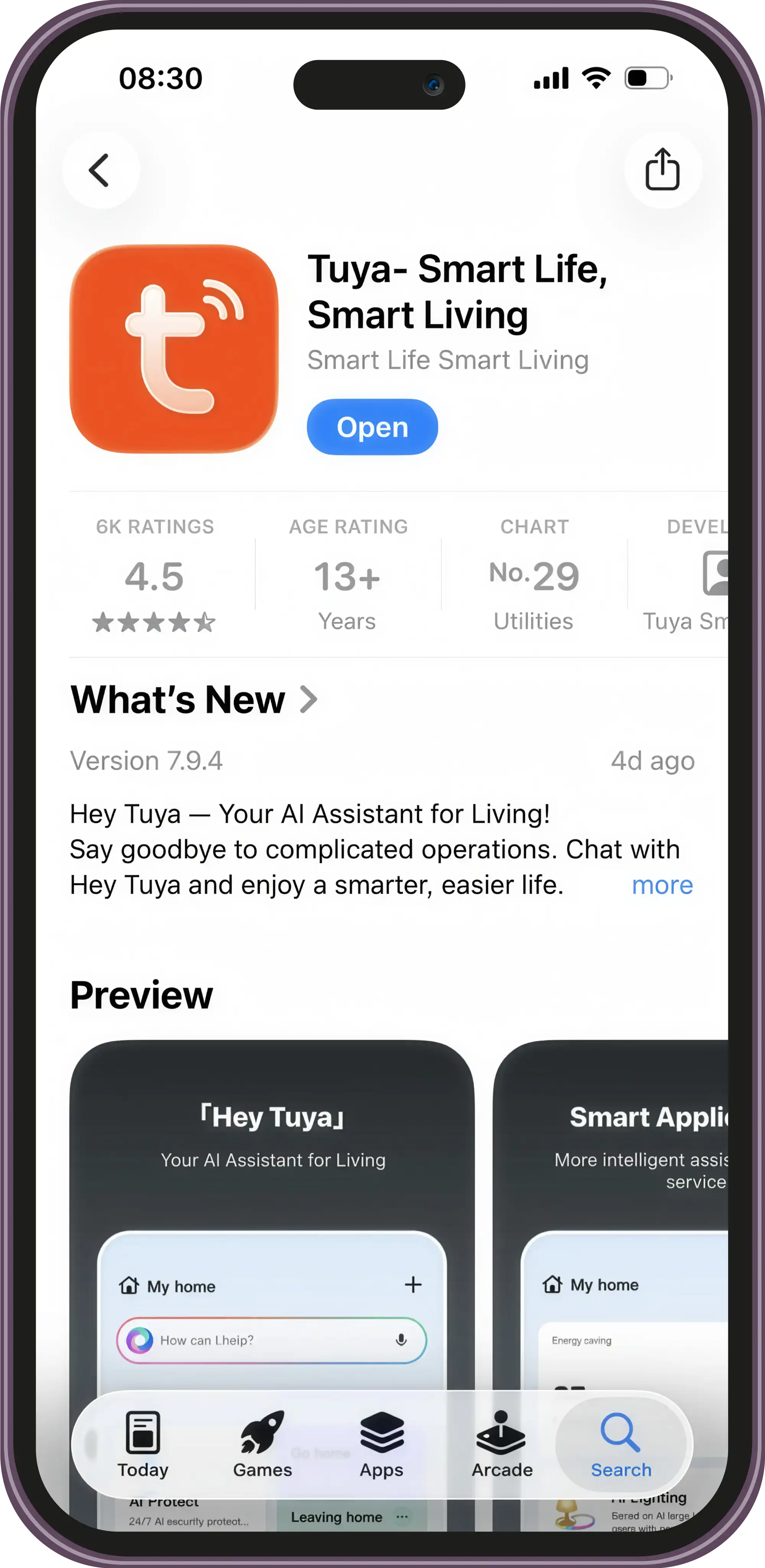
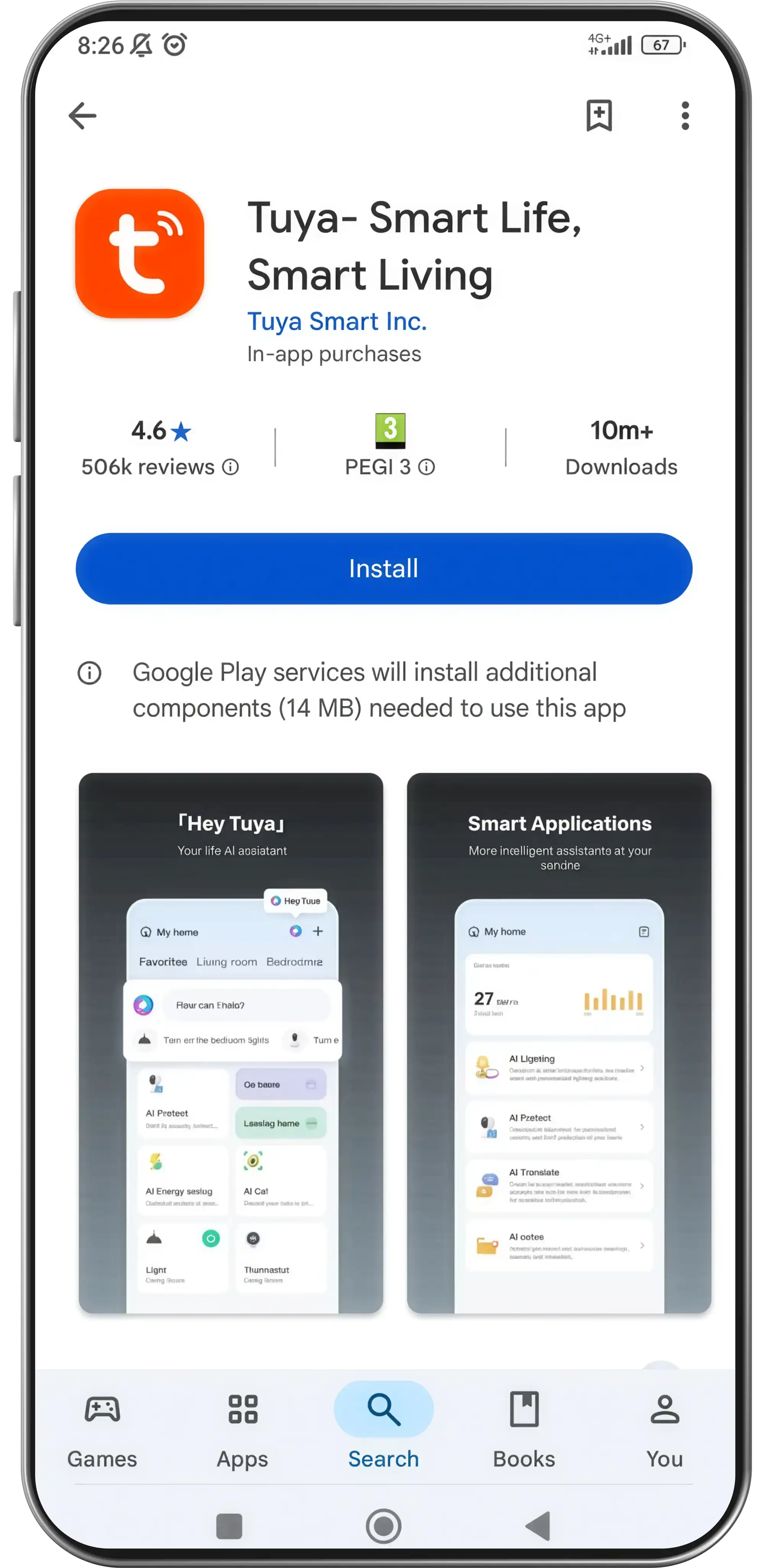
Download the Tuya App
Top
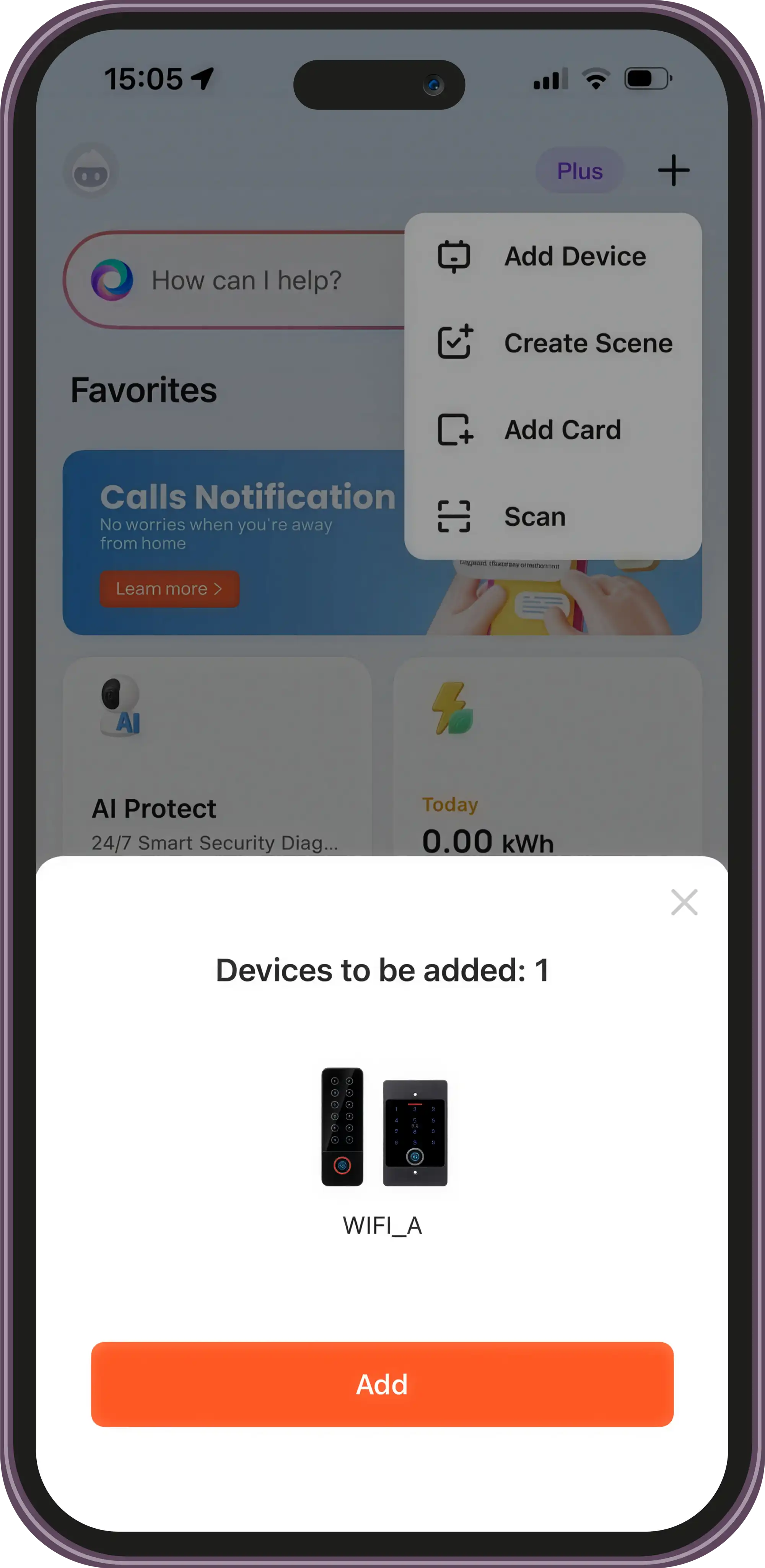
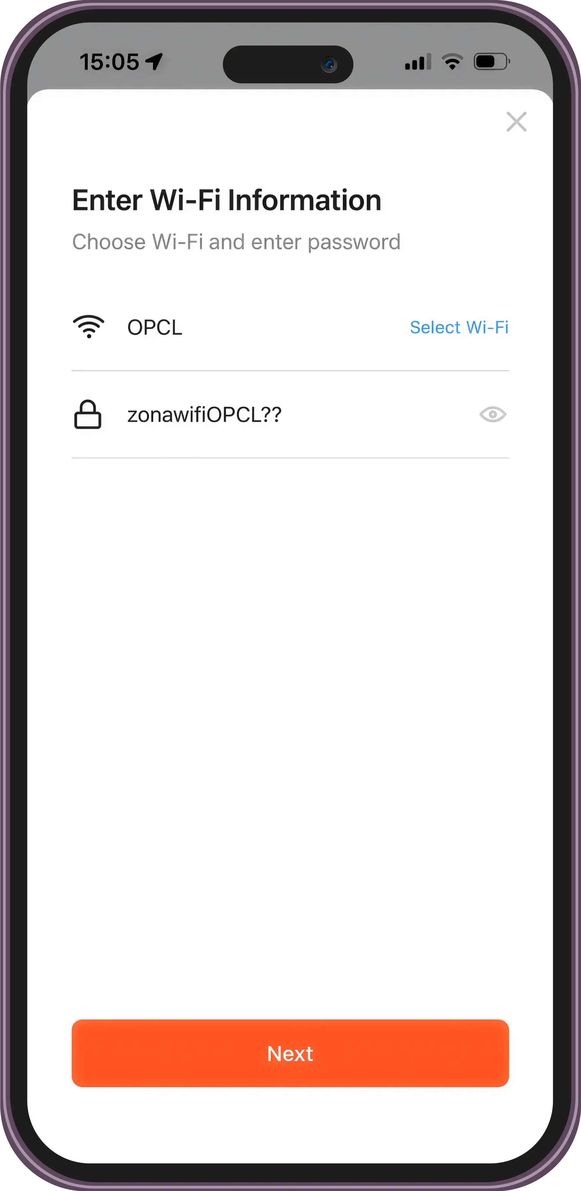
Connect Devices
Top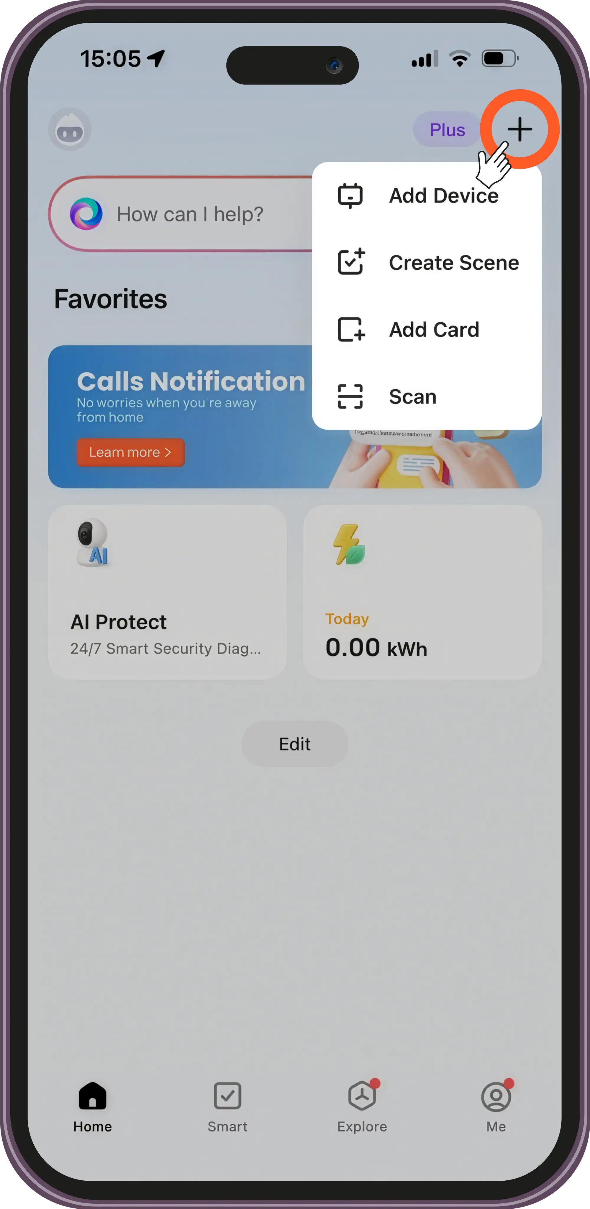
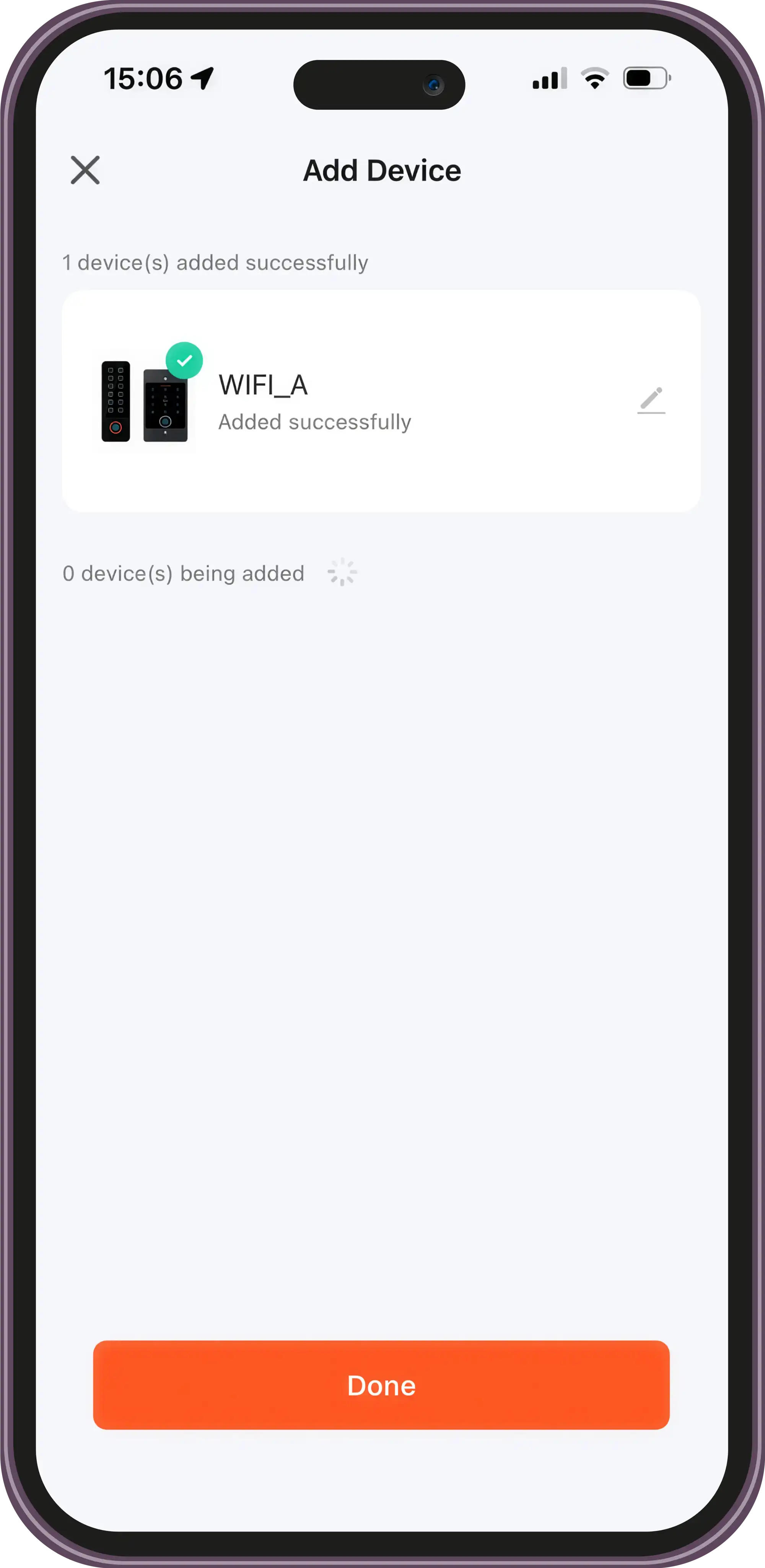
Open door from Tuya App
Top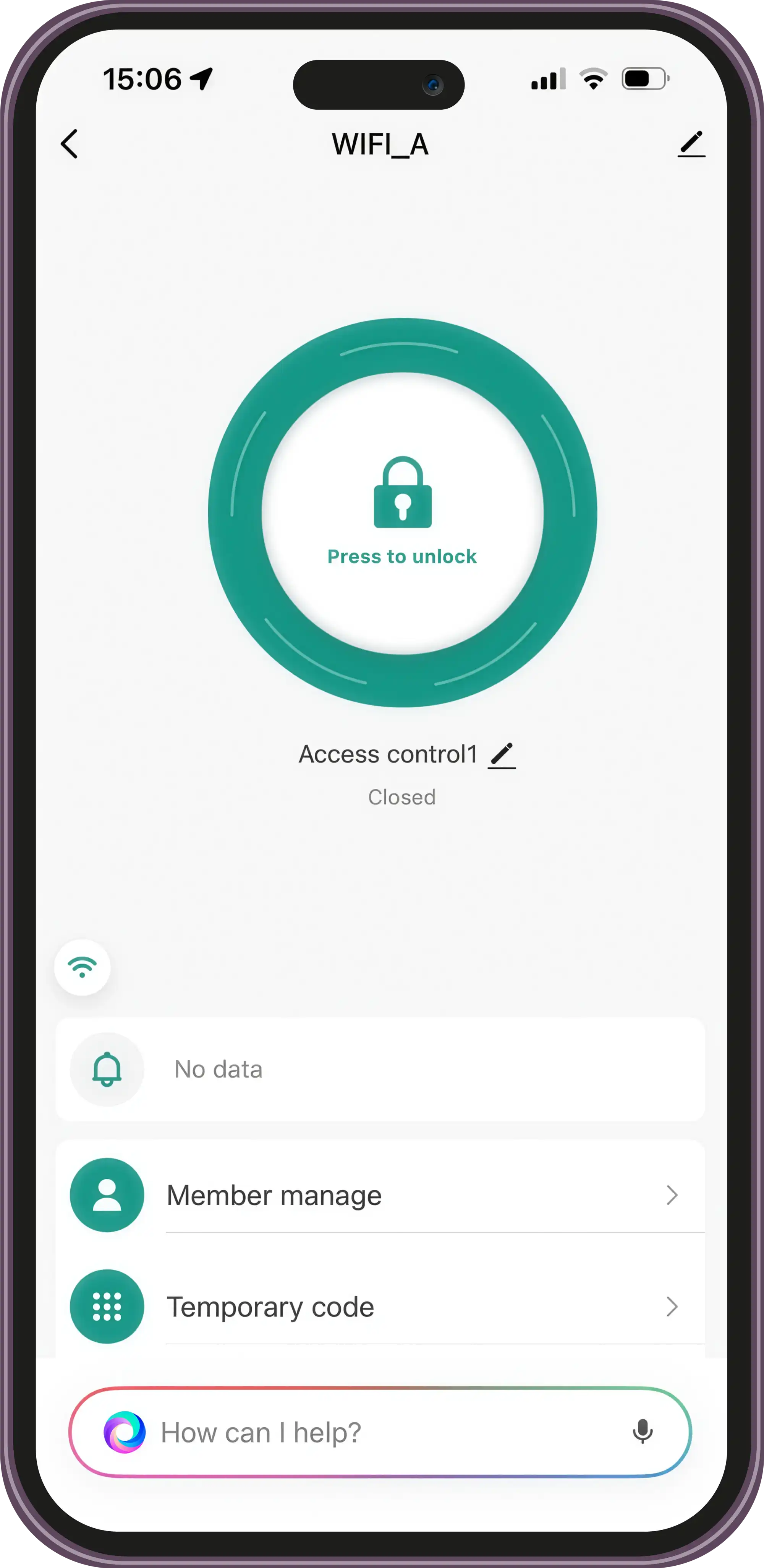
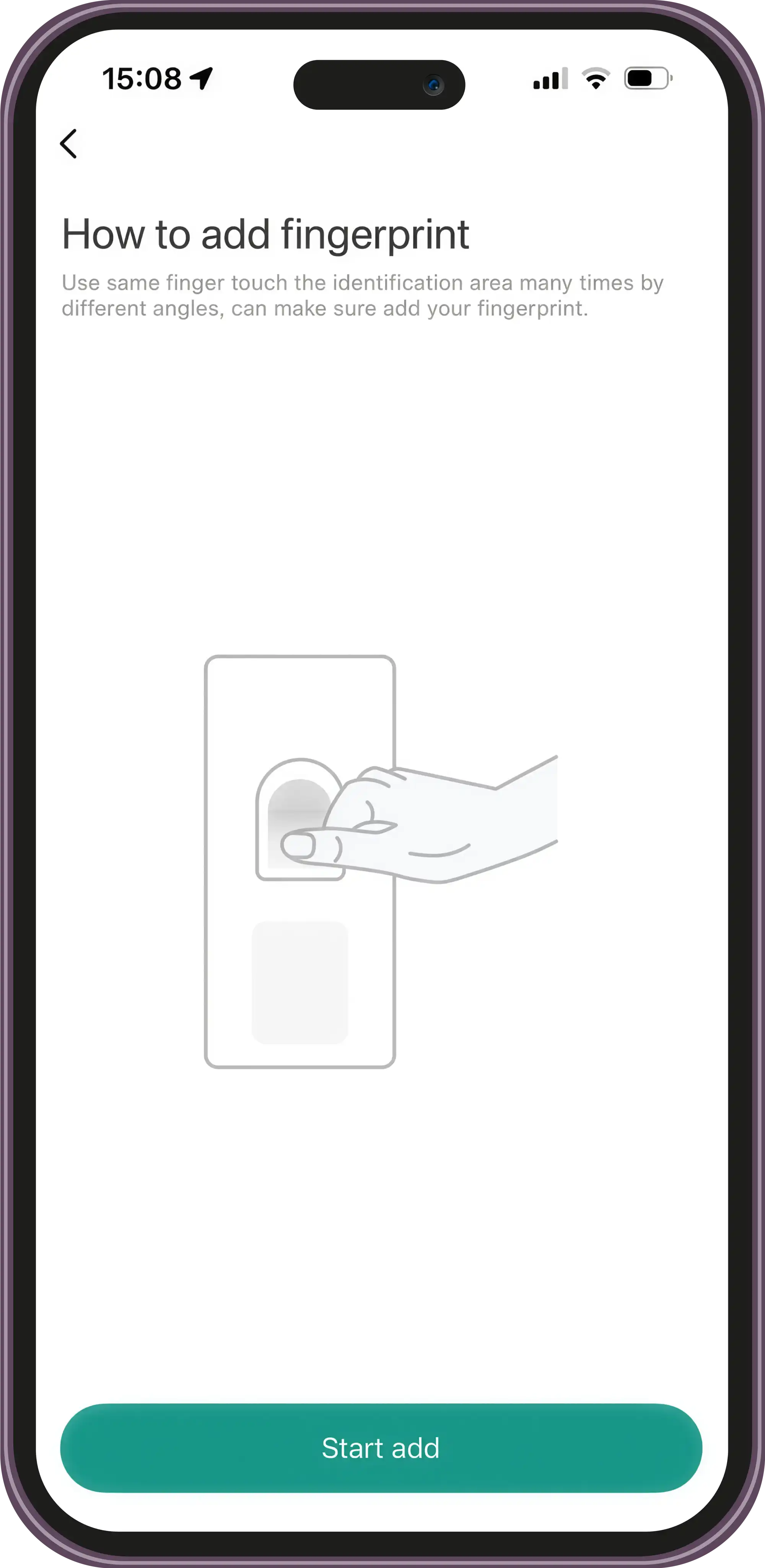
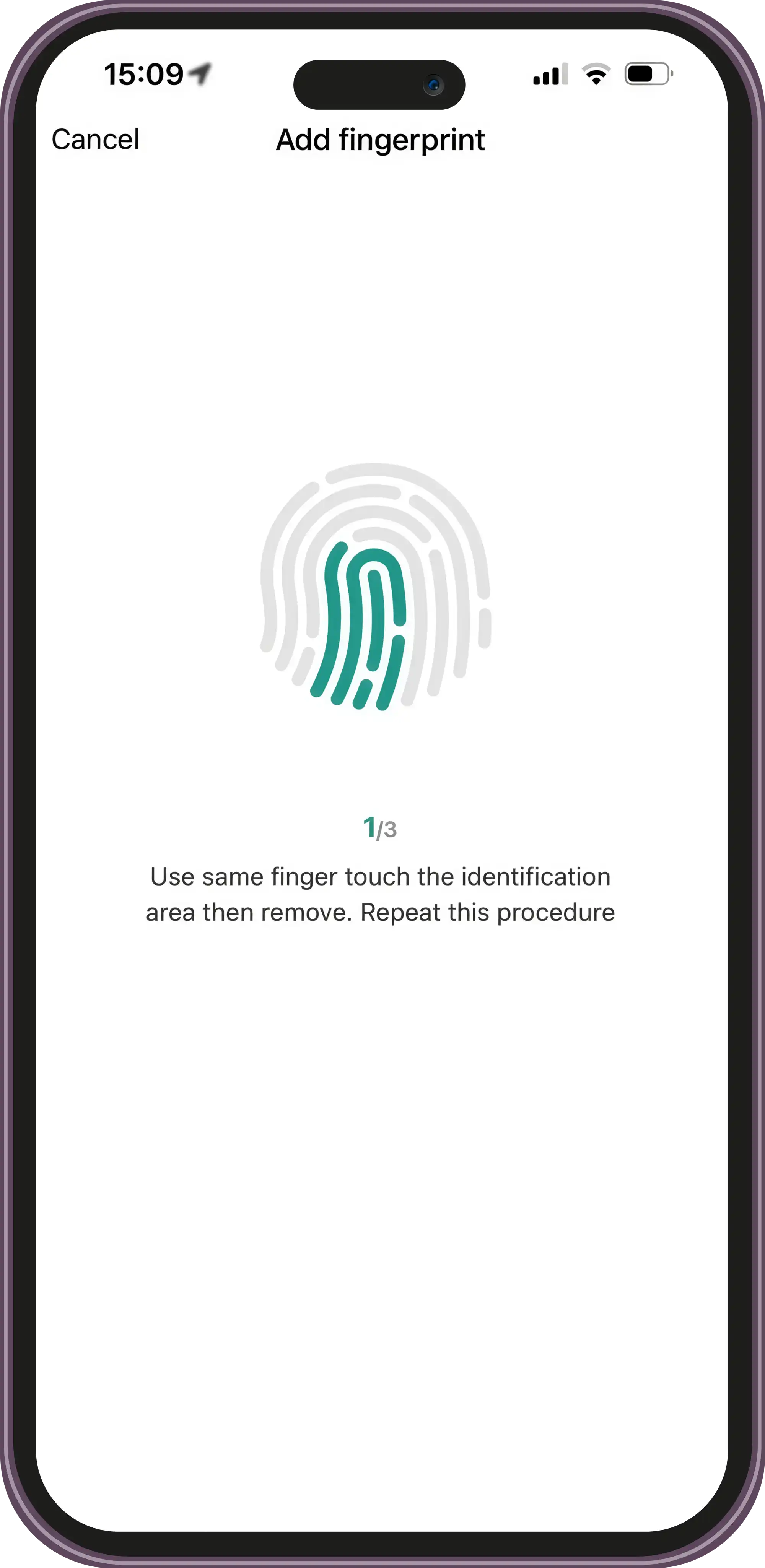
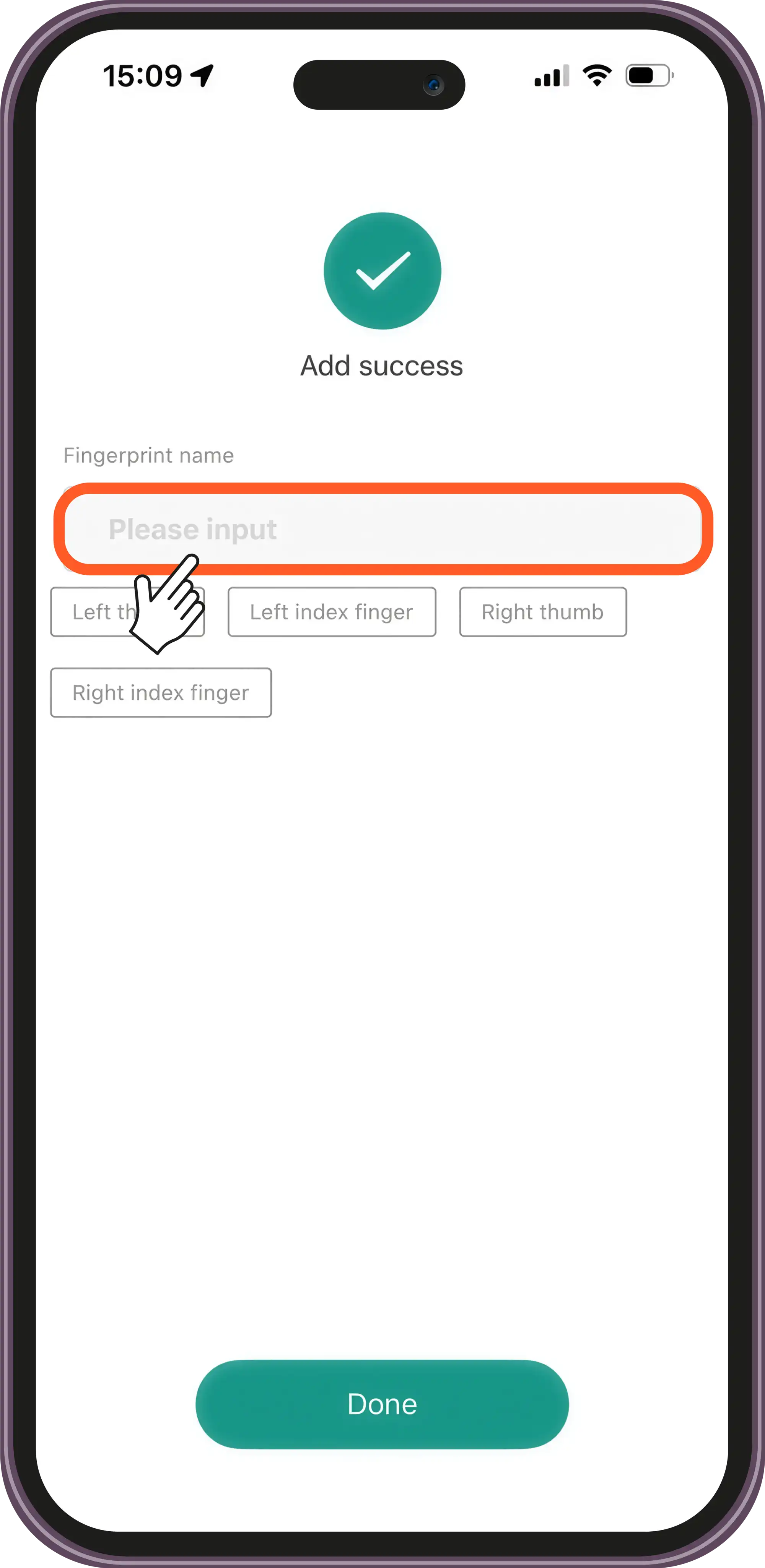
Add a Fingerprint
Top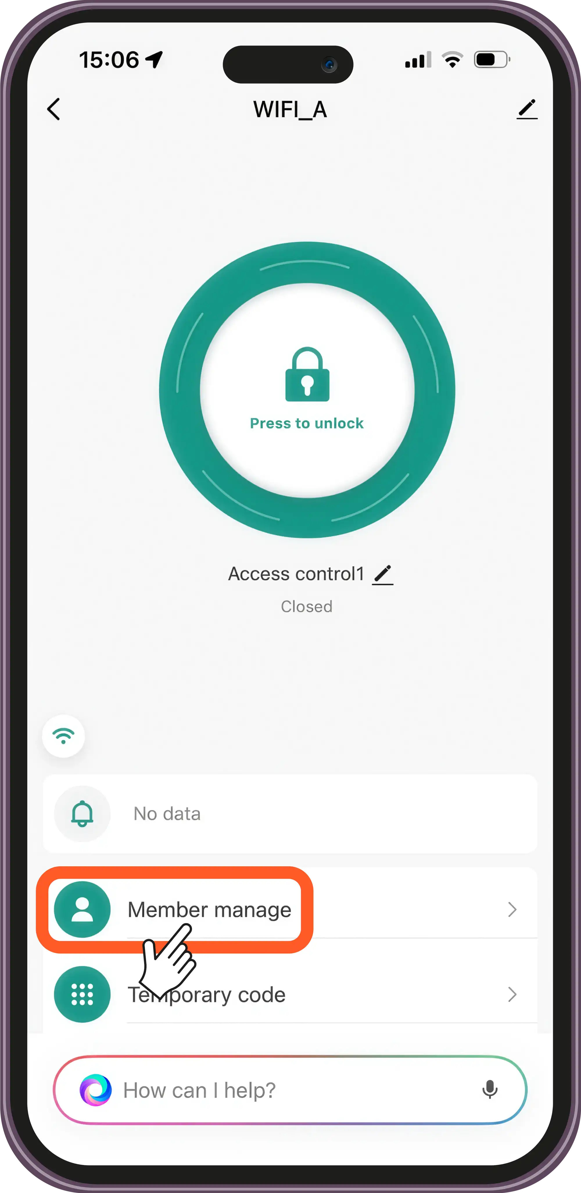
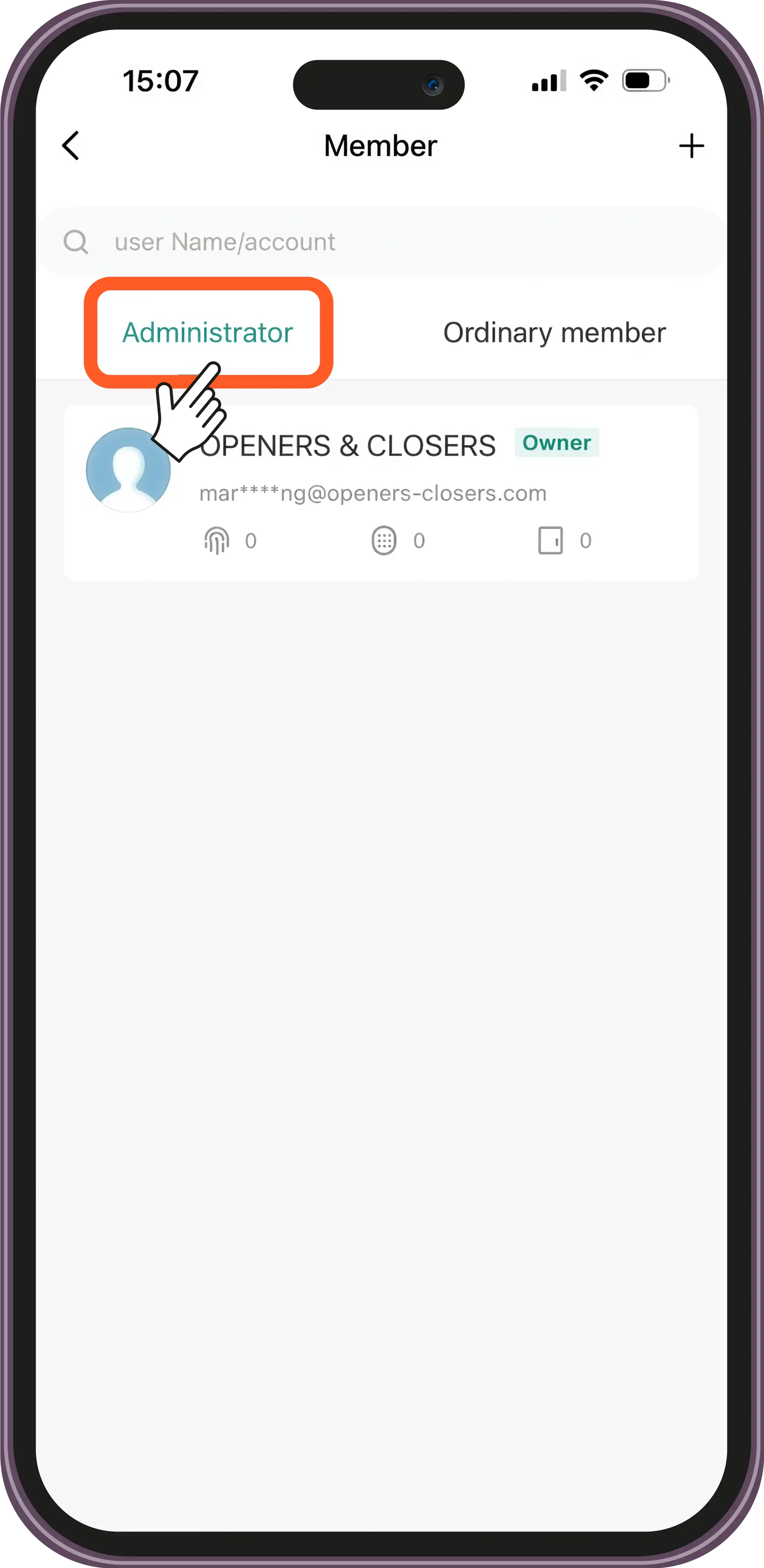

Add a Code
Top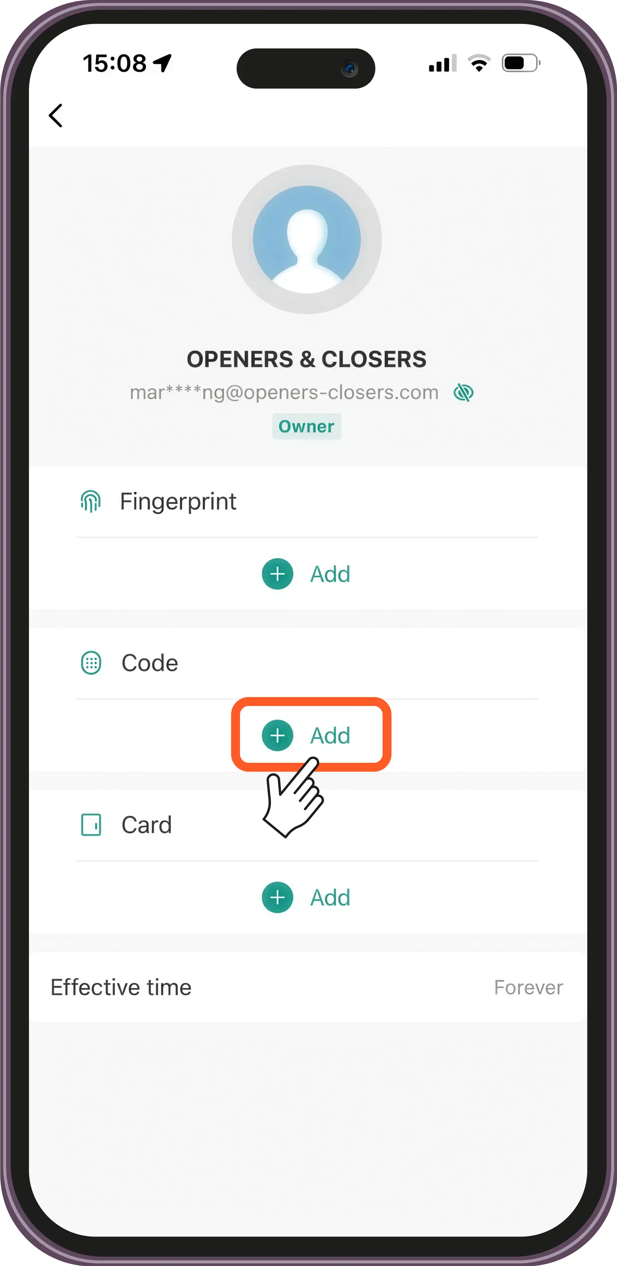
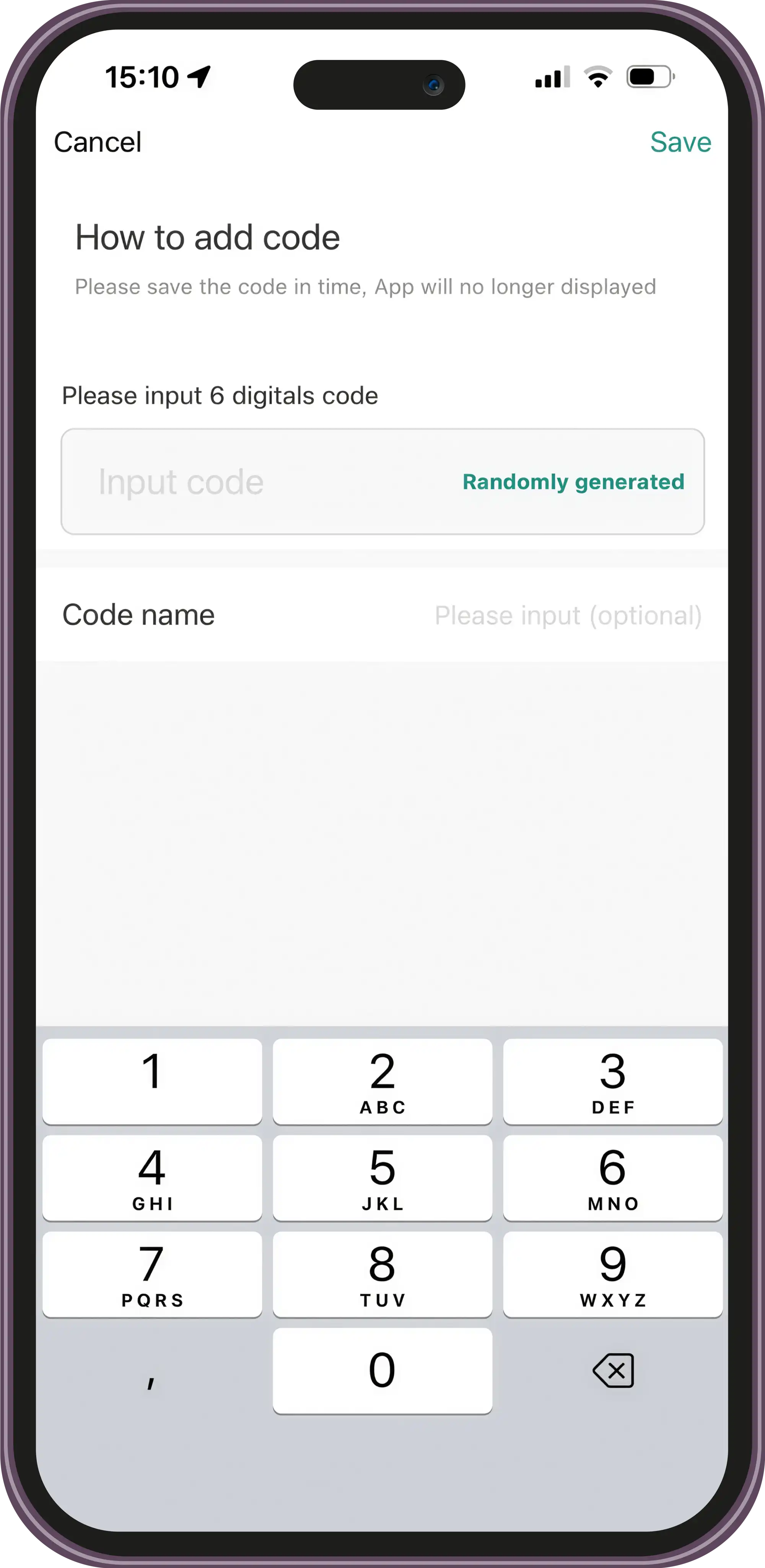
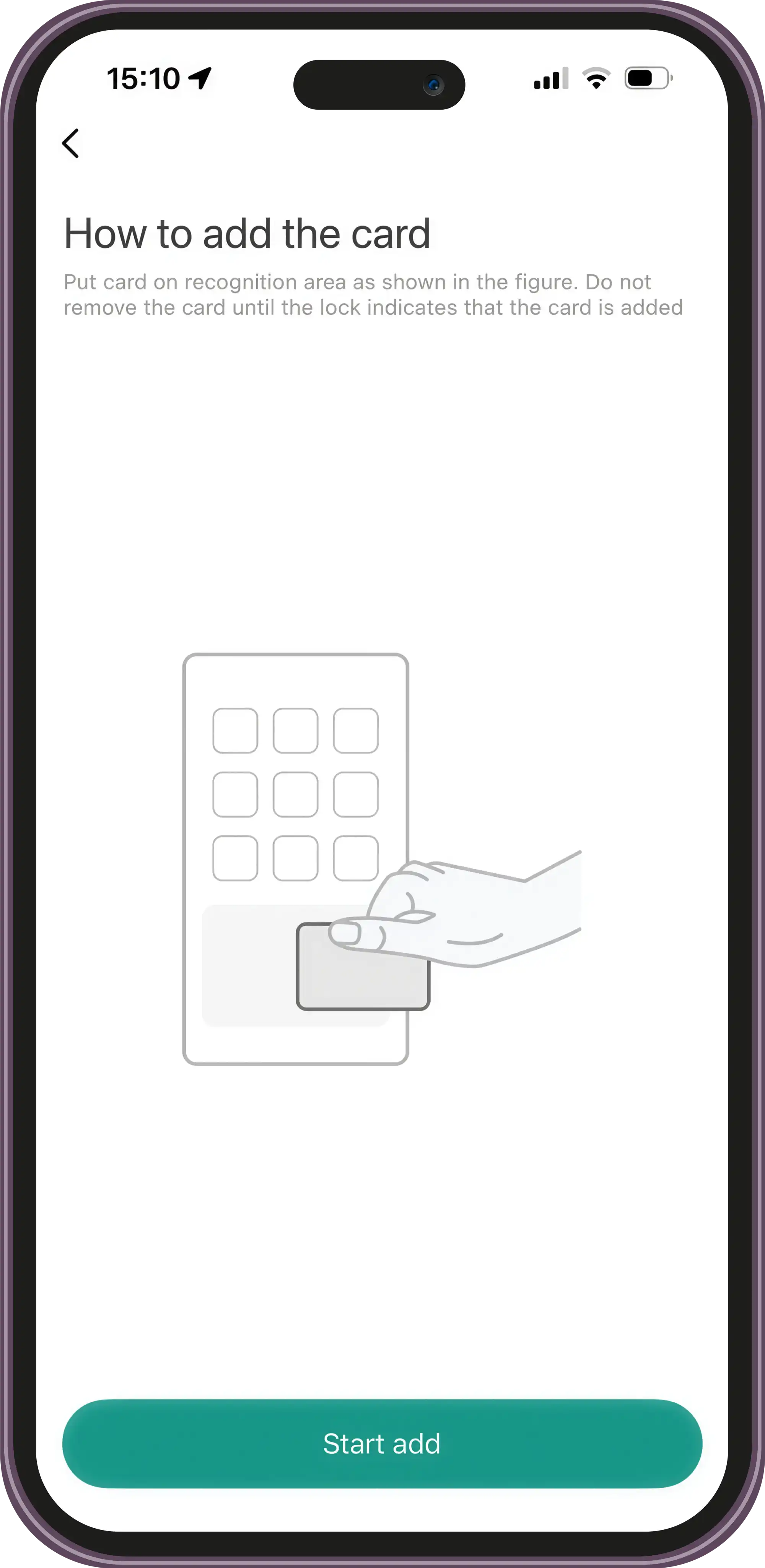
Add a Card
Top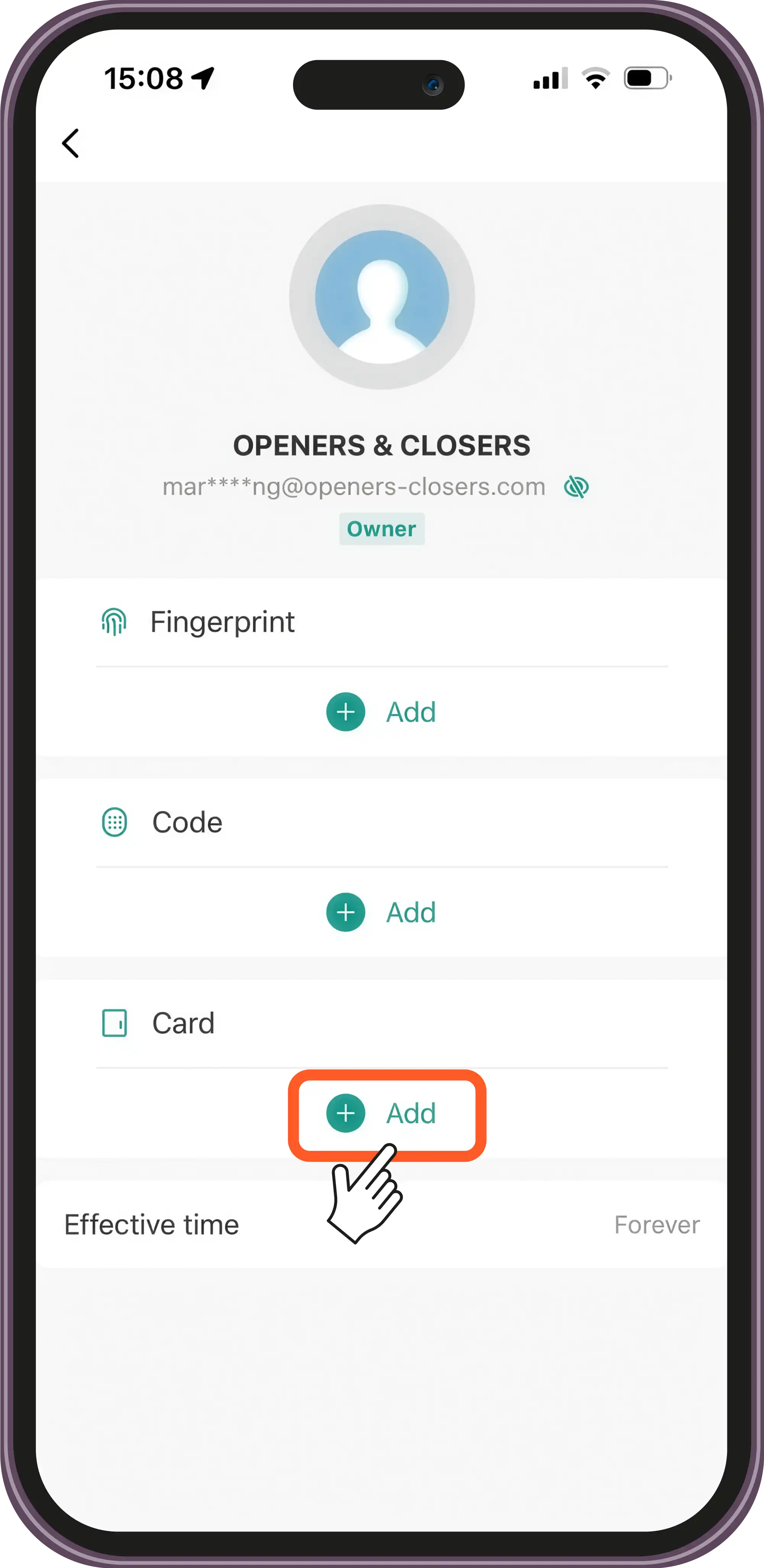
Add a User
Top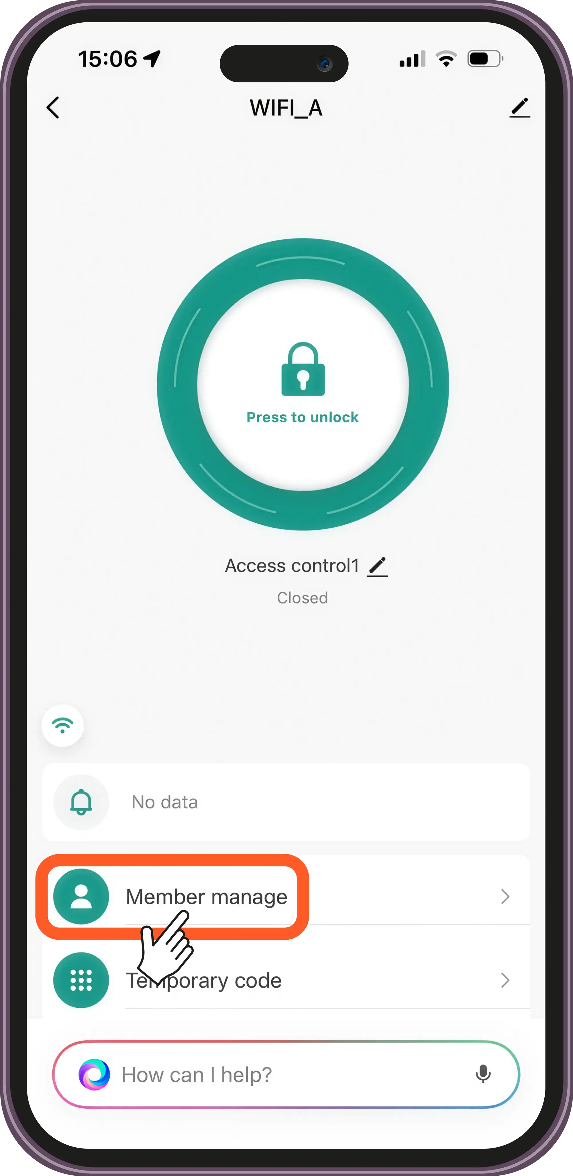
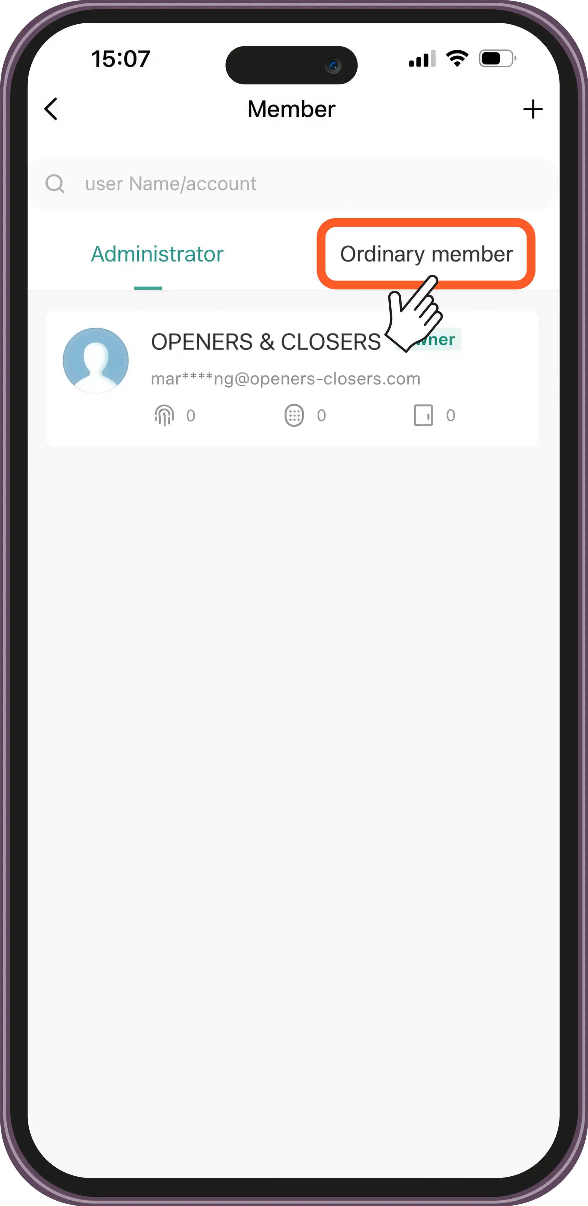
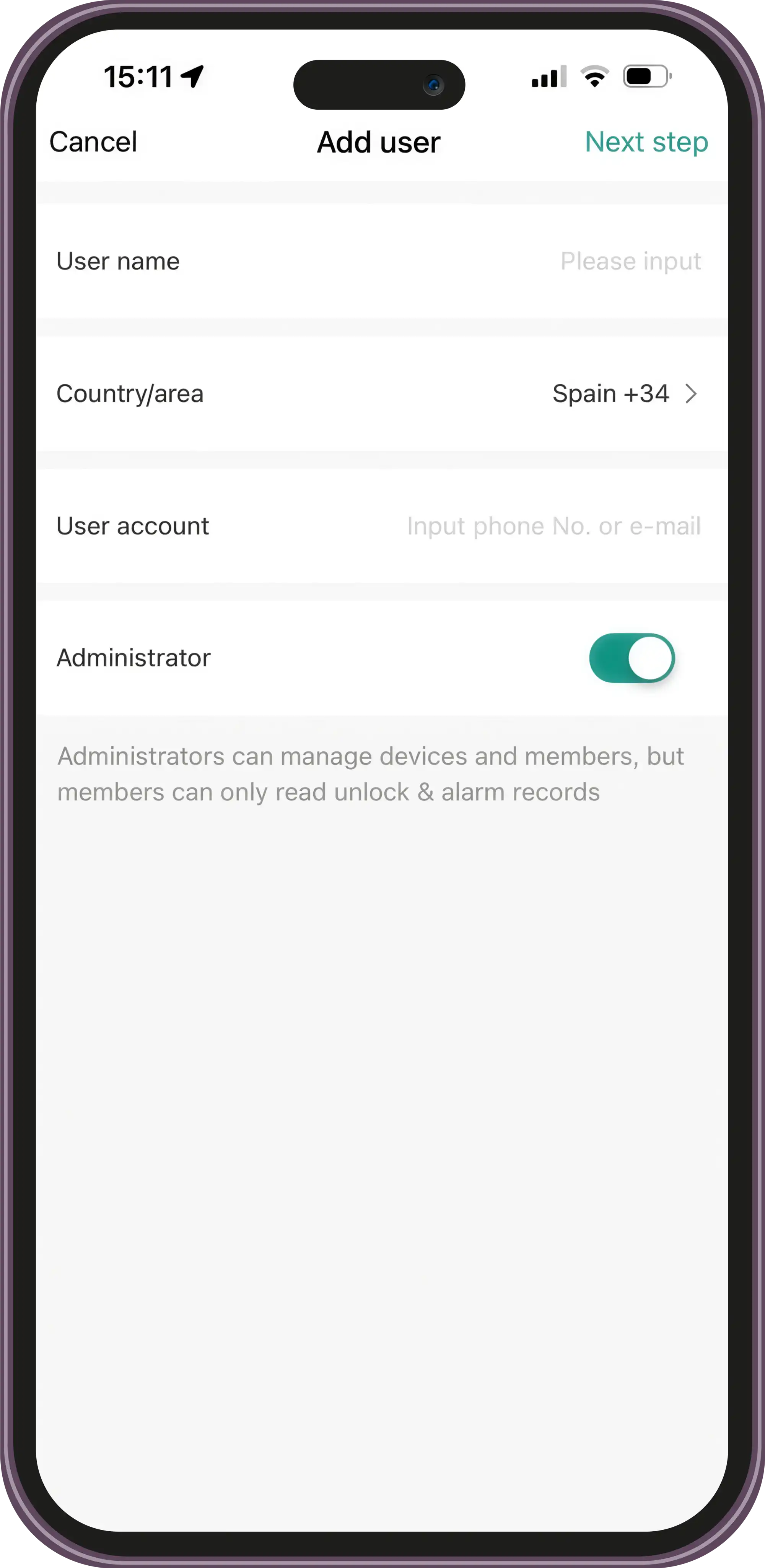
Add a Temporary Code
Top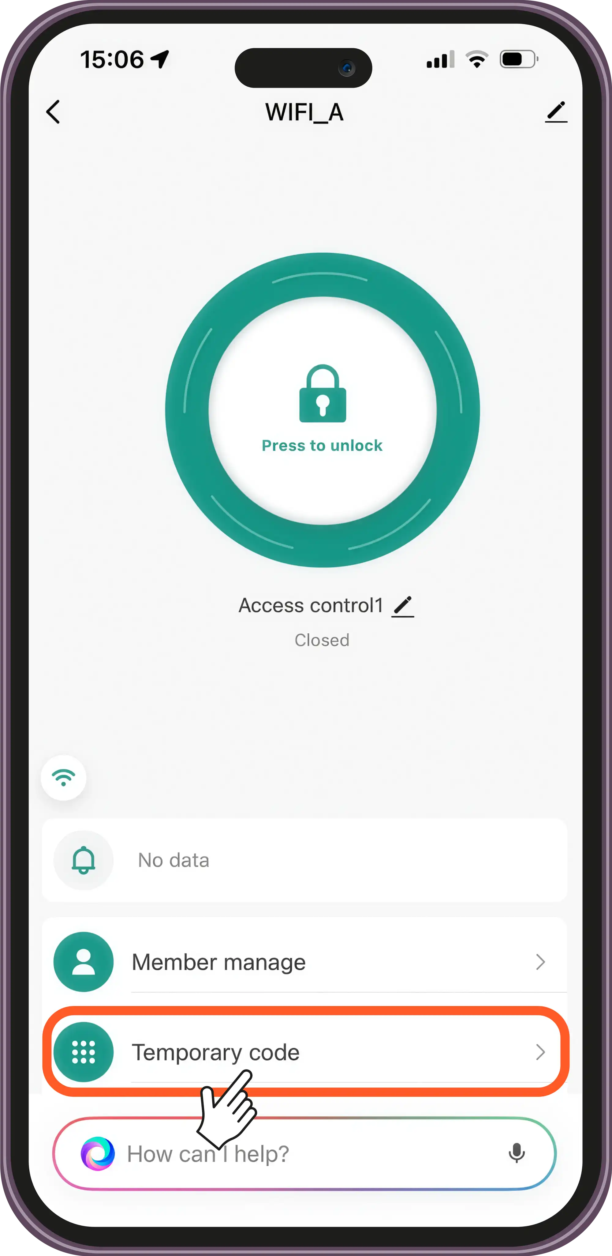
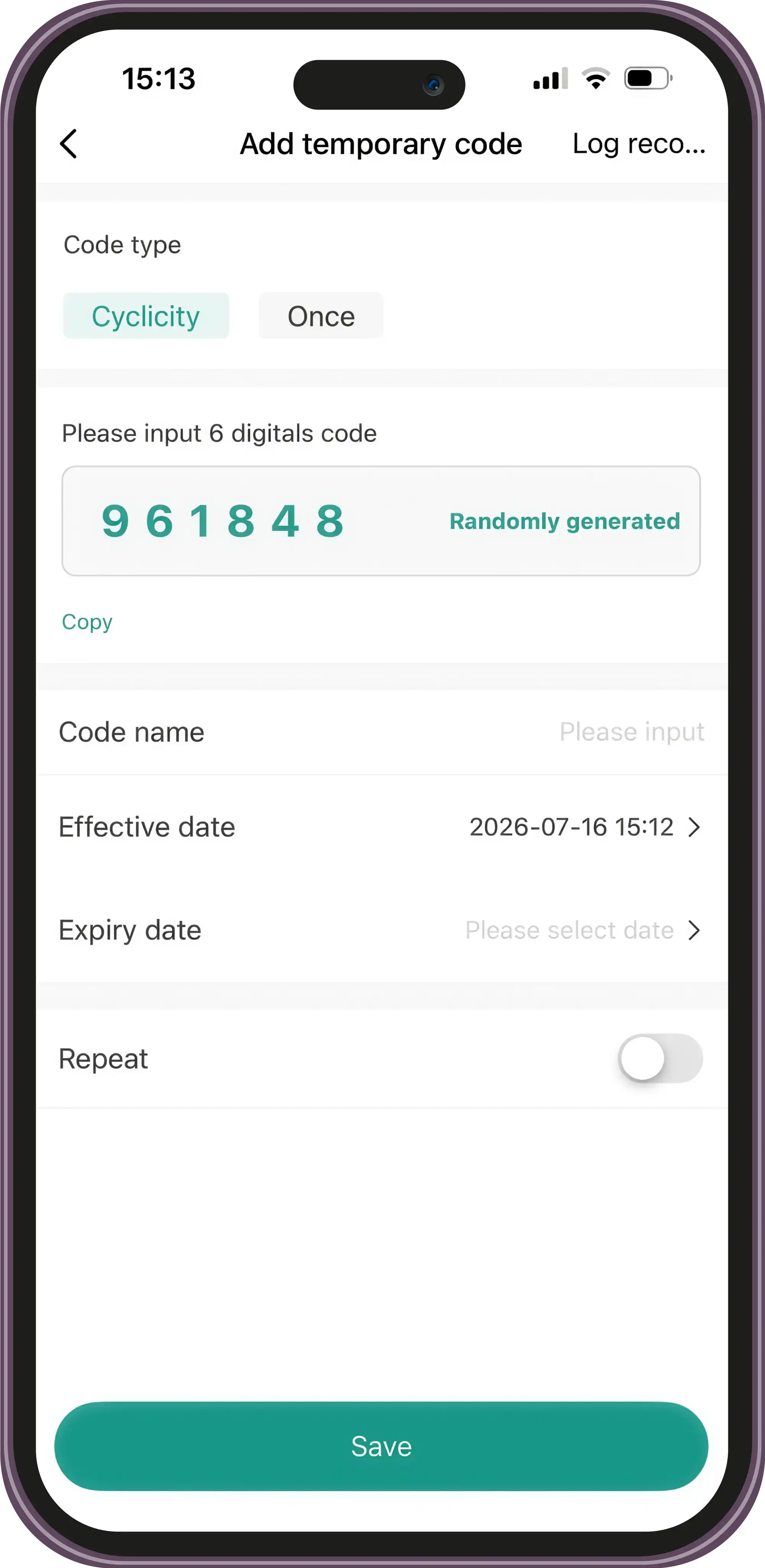
Access History
Top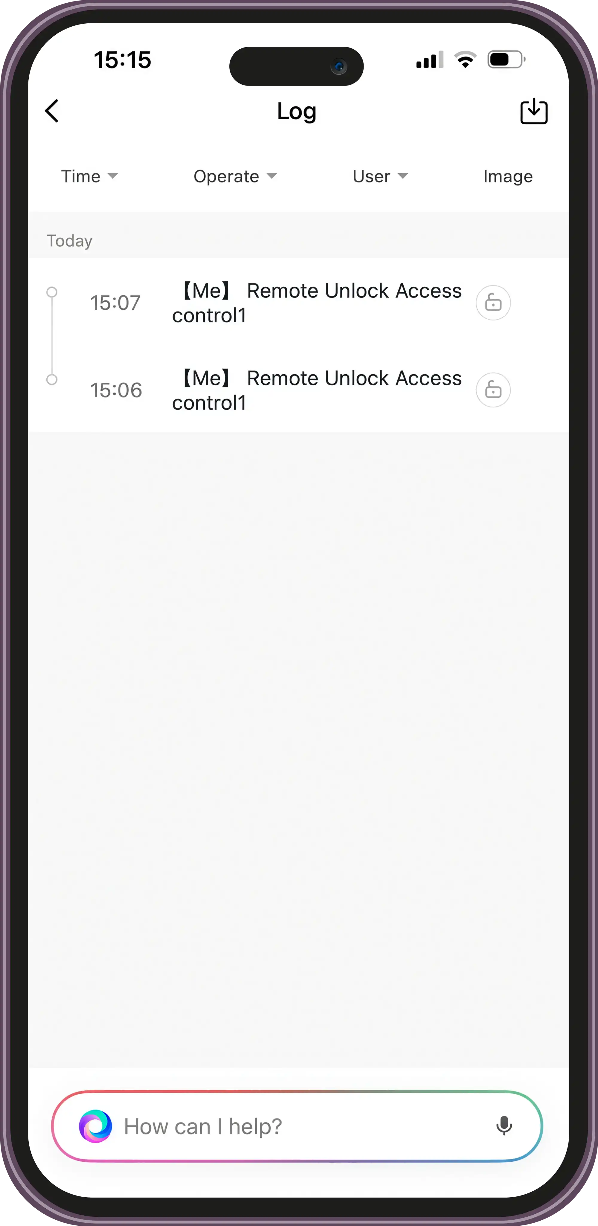
Device Update
Top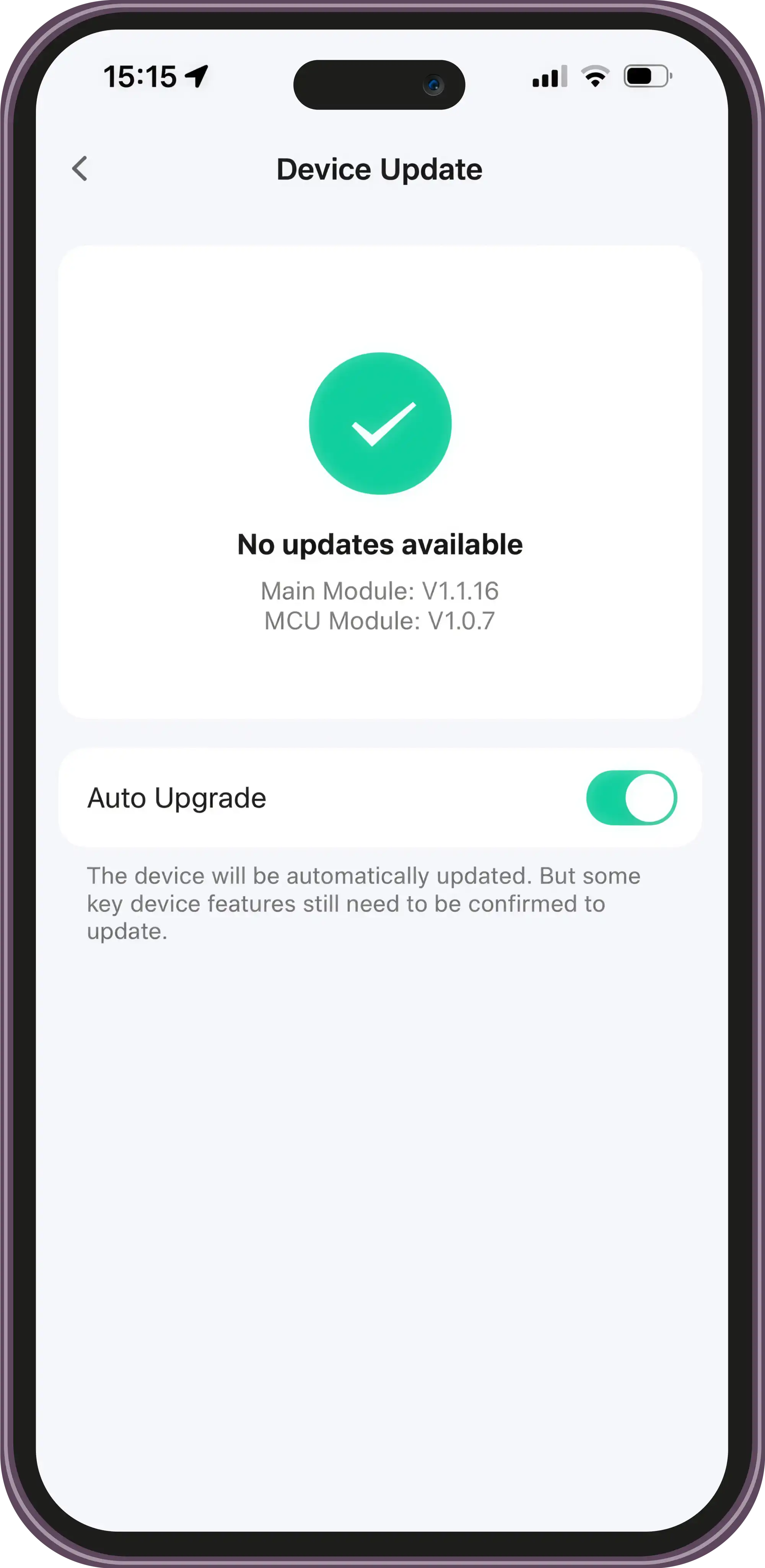
Contact Technical Support
Can't find what you're looking for? Our technical support team can help.
Get Help