Electric Mortise Lock
Series A Instruction Manual

Read before installation or use
TopRead Before Installing or Using This Device
This device has been designed for integration into professional access control systems in residential, commercial, or industrial buildings. It must only be installed and handled by qualified technical personnel, in accordance with the manufacturer's specifications. Improper use, unauthorised handling, or incorrect installation may cause serious harm to persons or property, and will void both the warranty and the manufacturer's liability.
Electrical Safety
Before connecting, disconnecting, or intervening with the device, ensure the power supply is completely switched off. Although this product operates at low voltage (e.g. 12–24 VDC), improper handling can cause short circuits, door damage, overheating, or risk of electric shock.
Intended Use and Compatibility
This device is suitable for wooden, metal, or aluminium doors, depending on the model. Certain models are certified for use on fire doors and emergency exits. Always verify the specific certifications and compatibility before installation. Use in environments exposed to water, heavy dust, or aggressive chemical agents is not recommended unless the device is properly certified (e.g. IP65, IP68 etc.).
Maintenance and Use
Do not open, modify, or tamper with the interior of the device. Any unauthorised intervention will automatically void the warranty. Cleaning should be carried out using soft cloths and non-abrasive products. Periodic maintenance by a qualified technician is recommended, particularly in high-usage environments.
Limited Warranty
This product is covered by a commercial warranty against manufacturing defects for the period specified by Openers & Closers. The warranty does not cover normal wear and tear, incorrect installation, tampering, mechanical impacts, or unsuitable environmental conditions. Openers & Closers shall not be held liable for indirect damage, financial loss, or harm resulting from improper or non-compliant use.
Regulations and Compliance
This product complies, where applicable, with relevant regulations in each market (e.g. CE, RoHS, WEEE, UL 294, NFPA-80, EN 14846). Refer to the product labelling and technical documentation to confirm specific certifications.
Disposal and Recycling
This device contains electronic components and must not be disposed of with household waste. It must be taken to an authorised collection point for electrical and electronic equipment (WEEE). The crossed-out wheeled bin symbol indicates this legal requirement. The packaging is recyclable and should be disposed of in accordance with local regulations.
Intellectual Property and Documentation
The content of this manual, as well as the technology integrated into the product, is protected by intellectual and industrial property rights. Its reproduction, distribution, translation, or modification is prohibited without the express authorisation of Openers & Closers.
Before starting the installation
TopRead the following carefully before installing
- Use the A1-basic cable (2 x 1.5 mm + 3 x 0.22 mm - Shielded)
- Use a 24 V DC power supply, with a minimum of 2.5 A per lock.
- The distance between the power supply and the lock must not exceed 25 meters.
- Ensure the distance between the lock and the strike plate is at least 2 mm and at most 6 mm.
- The lock and strike plate must be installed so that they are perfectly aligned (when the door is closed, they must be aligned laterally and in height).
- There must be no friction on the bolt when it opens and closes (this must be tested after installing the rubber seals on the profile).
- The holes where the cylinder is inserted must be long enough to allow for installation without forcing.
- It is strictly prohibited to file the door once the lock is installed! The electromagnet can attract filings when activated, damaging the coil.
- Make sure the door is equipped with suitable hinges (appropriate for its size and weight) to prevent it from sagging.
- Make sure the door is equipped with a suitable door closer (appropriate for the size and weight of the door).
Dimensions
Top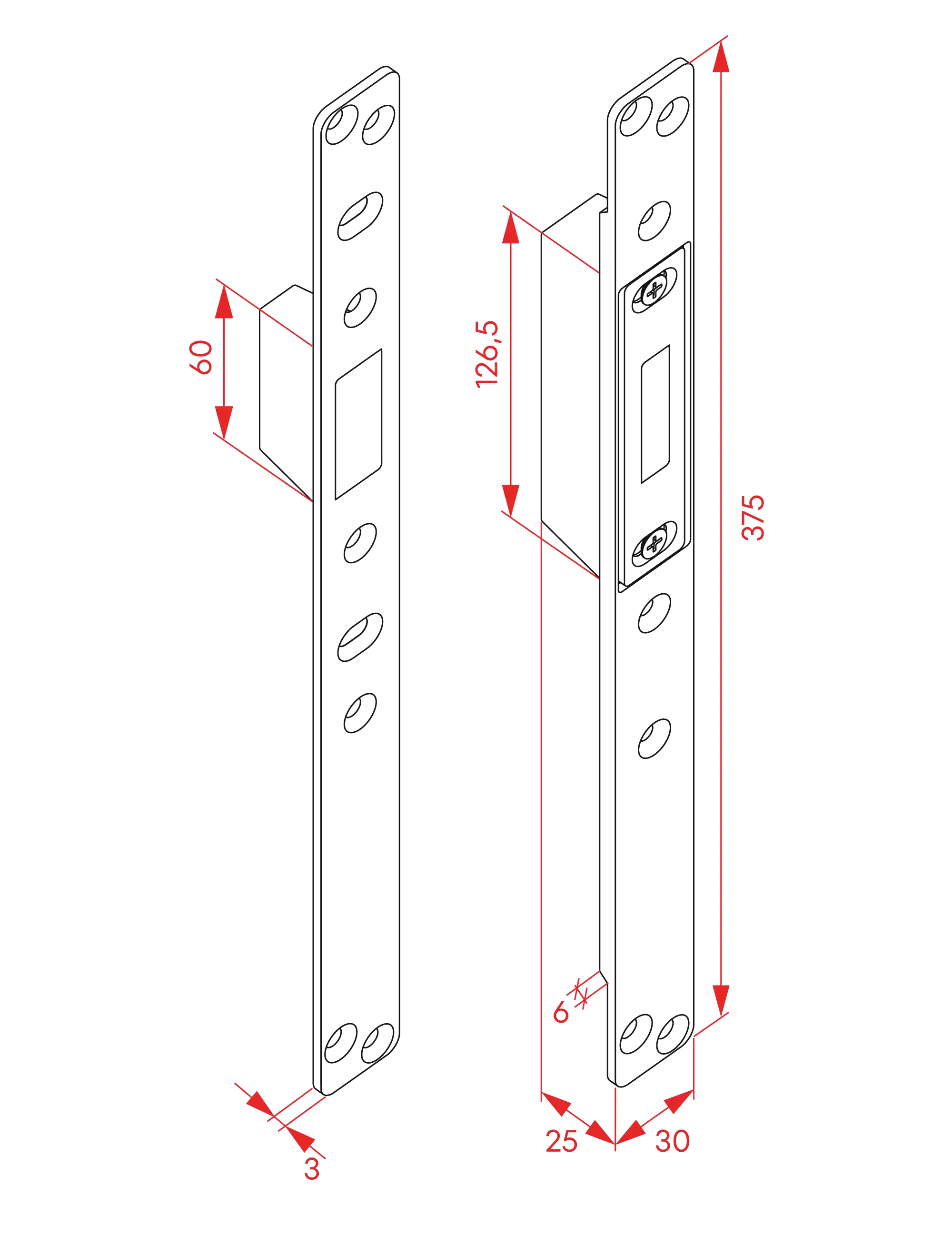
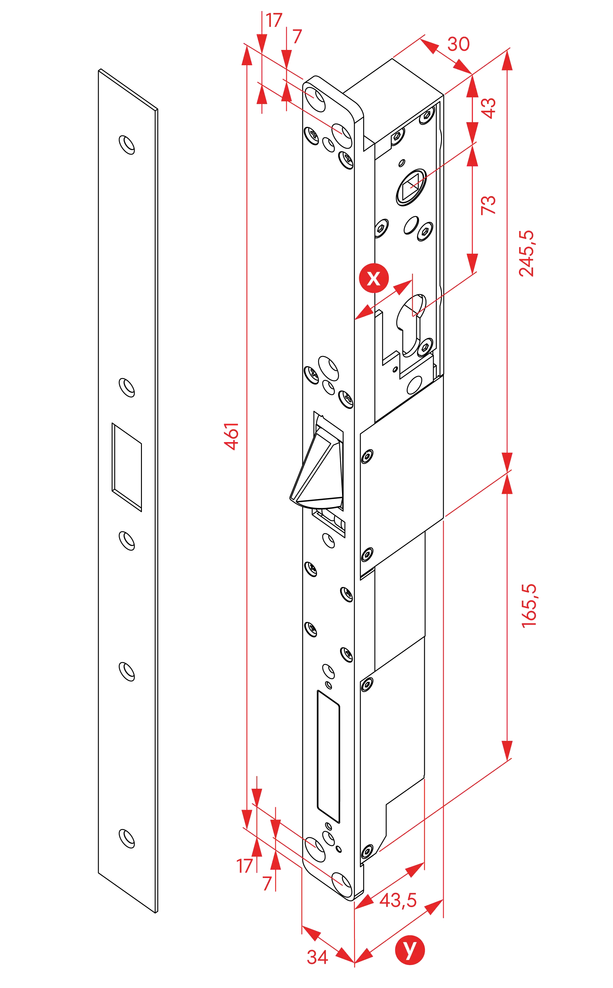
| (x) Pins | (y) Distance |
|---|---|
| 25mm | 43.5mm |
| 30mm | 48.5mm |
| 35mm | 53.5mm |
| 50mm | 68.5mm |
| 60mm | 78.5mm |
Installation
Top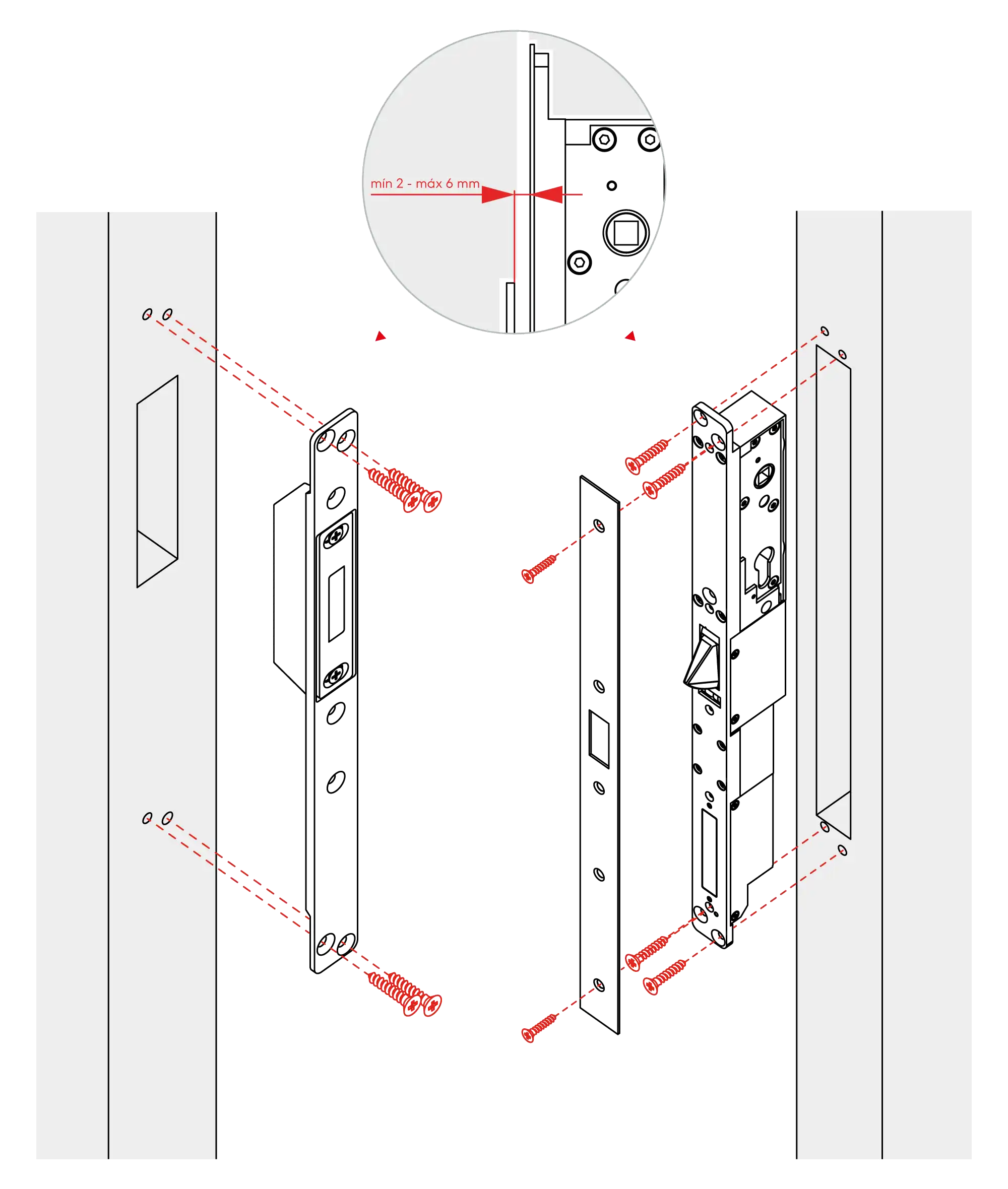
Wiring diagram
Top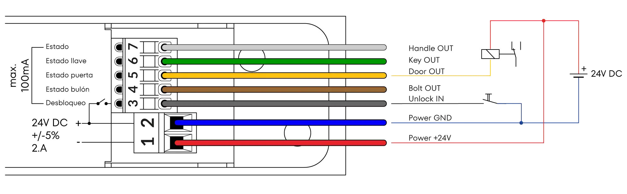
Contact Technical Support
Can't find what you're looking for? Our technical support team can help.
Get Help